Carrier 38AK007 User Manual
Installation, start-up and service instructions, A warning
Attention! The text in this document has been recognized automatically. To view the original document, you can use the "Original mode".
HEATING & COOLING
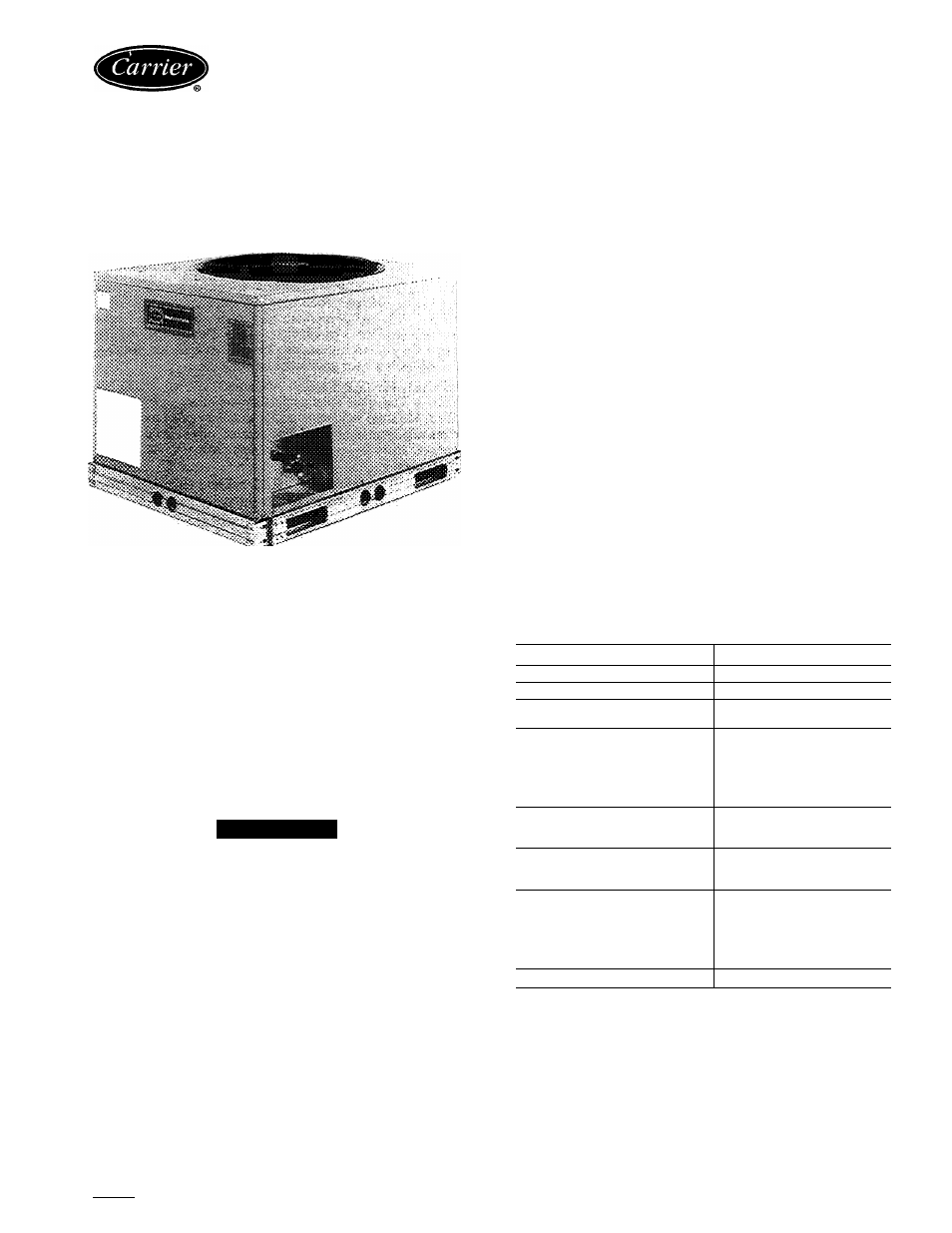
38AK007
Air-Cooled Condensing Unit
Installation, Start-Up and Service
Instructions
SAFETY COIMSIDERATIONS
Installing and servicing air-conditioning equipment can
be hazardous due to system pressure and electrical compo
nents. Only trained and qualified service personnel should
install or service air-conditioning equipment.
When working on air-conditioning equipment, observe
precautions in literature and on tags and labels attached to
unit.
Follow all safety codes. Wear safety glasses and work
gloves. Use quenching cloth for brazing operations. Have
fire extinguisher available. Read these instructions
thor
oughly. Consult local building codes and National Electri
cal Code (NEC) for special installation requirements.
A WARNING
Before installing or servicing system, always turn off
main power to system. There may be more than one
disconnect switch. Electrical shock can cause personal
injury.
INSTALLATION
Step 1 — Complete Pre-Installation Checks
UNCRATE UNIT — Remove unit packaging except for
the top skid assembly and wood bumpers, which should be
left in place until after unit is rigged into place.
INSPECT SHIPMENT — File claim with shipping com
pany if shipment is damaged or incomplete.
CONSIDER SYSTEM REQUIREMENTS
• Consult local building codes and NEC for special instal
lation requirements.
•
Allow sufficient space for airflow clearance, wiring,
refrigerant piping, and servicing unit. See Eig. 1 and
Table 1.
• Locate unit so that condenser airflow is unrestricted on
all sides and above. Refer to Fig. 1.
• Unit may be mounted on a level pad directly on base
rails or mounted on raised pads at support points. See
Table 2 for weight distribution based on recommended
support points.
NOTE: If vibration isolators are required for a particular in
stallation, use data in Table 2 to make proper selection.
Table 1 — Physical Data
UNIT 38AK
007
OPER WEIGHT (lb)
340
REFRIGERANT*
22
COMPRESSOR
on (oz)
65
CONDENSER AIR FAN
Number...Rpm 60 Hz
50 Hz
Diameter (in.)
Motor Hp (NEMA)
Nominal Cfm Total
Propeller; Direct Drive
1.. .850
1.. 708
26
Vs
3800
CONDENSER COIL
Face Area (sq ft)
Storage Capacity (lb)t
12 24
11.264
CONNECTIONS (sweat)
Suction (in.)
Liquid (In.)
1V8
V
2
CONTROLS
Pressurestat Settings
High Cutout
Cut-in
Low Cutout
Cut-in
426 ± 7 psig
320 ± 20 psig
7 ± 3 psig
22 ± 5 psig
FUSIBLE PLUG
200 F
‘Unit is factory supplied with holding charge only.
fStorage capacity of condenser coil with coil 80% full of liquid R-22
at 124 F
Manufacturer reserves the right to discontinue, or change at any time, specifications or designs without notice and without incurring obligations.
Book|1 |4
PC 111
Catalog No 633-809
Printed in U.S A
Form 38AK-2SI
Pg 1
6-92
Replaces: New
Tab 3a 2a
Document Outline
- Installation, Start-Up and Service
- Instructions
- SAFETY COIMSIDERATIONS
- INSTALLATION
- Step 1 — Complete Pre-Installation Checks
- Step 2 - Rig and Mount the Unit
- Step 4 — Make Electrical Connections
- START-UP Preliminary Checks
- SERVICE
- Lubrication
- Condenser-Fan Adjustment (Fig. lO)
- TROUBLESHOOTING GUIDE
- COMPRESSOR DOES NOT RUN
- Contactor Open
- Contactor Closed
- COMPRESSOR CYCLES ON HIGH-PRESSURE SWITCH
- Condenser Fan On
- Condenser Fan Off
- COMPRESSOR CYCLES ON LOW-PRESSURE SWITCH
- Evaporator Air Fan Running
- Airflow Restricted
- Evaporator Air Fan Stopped
- COMPRESSOR RUNS BUT COOLING INSUFFICIENT
- Suction Pressure Low
- Suction Pressure High