Carrier, Installation – Carrier 50K User Manual
Page 3
Attention! The text in this document has been recognized automatically. To view the original document, you can use the "Original mode".
Carrier
INSTALLATION
50K
TABLE 4
High Press. Switch
Low Press. Switch
Refrig.
Cut-In
Cut-Out
Cut-In
Cut-Out
22
284
364
83
46
500
218
265
67
30
NOTE* If the liquid refrigerant bleeds from the
liquid level check port on the receiver but
there is stUl flashing at the sight glass,
there is an indication that there is a re
striction in the liquid line or filter-drier.
Let the system operate for 20 minutes to balance
out and recheck the refrigerant and oil levels.
SPORLAN SEE-ALL MOISTURE AND
LIQUID INDICATOR
The moisture and liquid indicator must be full of
liquid refrigerant to properly indicate the moisture
content of the refrigerant. Operate the system at
least 30 minutes before attempting to determine the
moisture reading.
CHARGING PROCEDURE
The receiver has a bleeder port at the top to bleed
non-condensables from the system. There has to
be sufficient refrigerant in the system to make a
liquid seal at the outlet of the receiver to trap the
non-condensables in the top of the receiver before
the bleeder port can be effective.
WIRING
The crankcase heater elements, heater relays, and
the condenser fan relays are to be field wired. See
Wiring Diagrams.
The compiete refrigerant system should be evacuated
with a good vacuum pump before charging with refrig
erant. When charging, connect a cylinder of refrig
erant through a tee to a gauge and to the gauge port
on the compressor service valve. Have the cylinder
in the upright position to admit vapor only. Admit re-
refrigerant to break the vacuum in the system. Start
the compressor and modulate the valve on the cylinder
to keep the suction pressure slightly under 50 psig.
Charge the system until liquid refrigerant will bleed
from the liquid level check port on the receiver and
also until the sight glass is clear. *
The crankcase heater relays are single pole, single
throw, normally closed, relays . Each crankcase
heater element is to be energized when its respec
tive compressor is "OFF.”
The condenser fan relays (S.P.S.T. Normally open)
are to be mounted per the condenser Installation In
structions . The control voltage is supplied by the
base unit. Follow the right wiring diagram so the
condenser fans wUl continue to run if the compres
sor is shut down by one of its protective devices
and the thermostat is stUl calling for cooling.
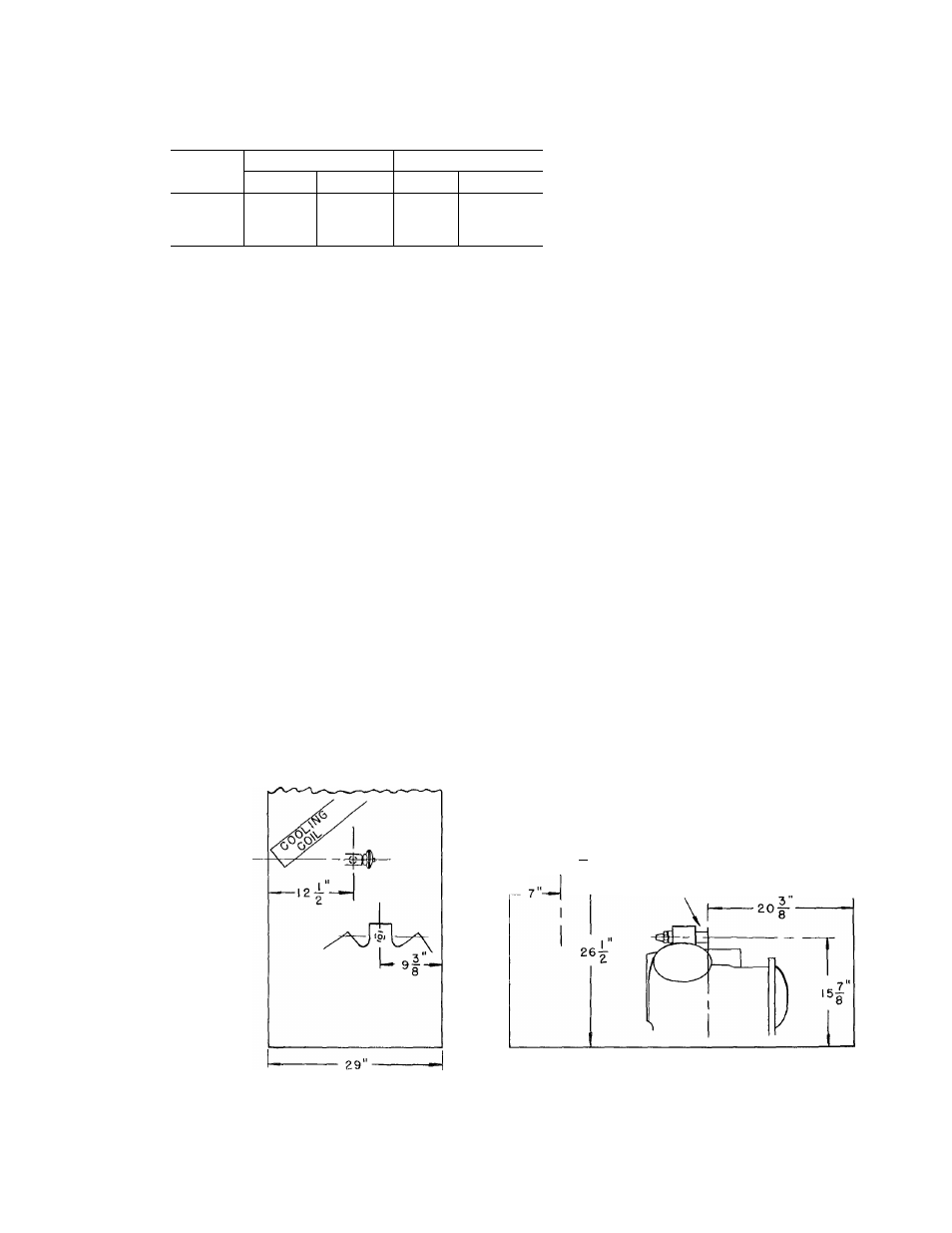
SIDE ELEVATION
FRONT ELEVATION
NOTE. ALL DIMENSIONS ARE TO
1
OUTSIDE OF CASING, NOT
I
TO OUTSIDE OF PANEL.
EXPANSION VALVE
EXPANSI
COMPRESSOR
DISCHARGE VALVE
48
FIG. 1 - LOCATION OF COMPRESSOR DISCHARGE AND LIQUID CONNECTIONS 50K8