4 549 remote annunciator – Winco DSE549 Remote Ennunciator User Manual
Page 9
P130 operators manual ISSUE 2 14/6/04 AM
9
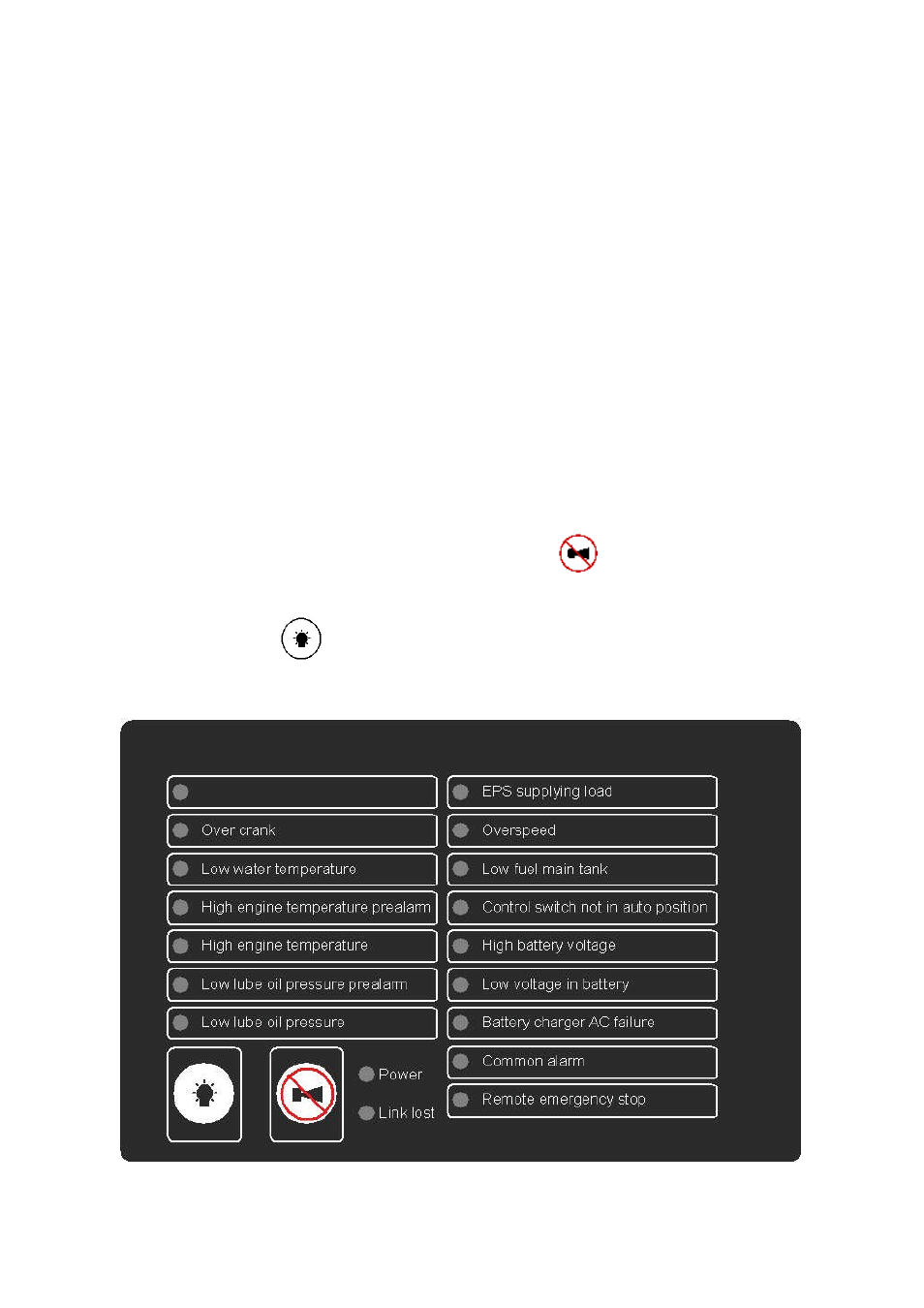
4 549 REMOTE ANNUNCIATOR
4.1 DESCRIPTION OF OPERATION
The model 549 remote annunciator is intended to help system manufacturers meet the
requirements of the NFPA110 level 1 specification by providing indication of the required
cont
r
ol
/
al
ar
m
st
at
us.
A
‘
spar
e’
channel
i
s
pr
ovi
ded
t
hat
be
conf
i
gur
ed
t
o
one
of
a
number
of
choi
ces
to help the system manufacturer meet more complex specifications.
The 549 is connected via a 4 core cable to the connector 2 socket of the DSE P130 input
expansion module.
For connection details, see the sections headed Terminal Description and Typical Wiring Diagram
elsewhere in this manual.
Correct connection of the 4 core cable to a correctly connected and operating P130 input
expansion module will illuminate the Power LED.
If the P130 input expansion module does not have DC power connected to it, or the 4 core cable is
not
cor
r
ect
l
y
t
er
mi
nat
ed,
t
he
549’
s
Power
LED
wi
l
l
r
emai
n
ext
i
ngui
shed.
Failure of the data signal to the 549 from the P130 (terminals B & C) will cause the Link Lost LED
to flash.
The 549 features an internal sounder that is activated upon detection of any of the channels (with
the exception of ‘
EPS
suppl
yi
ng
l
oad’
)
.
The sounder can be muted by pressing the integral alarm mute
button. Once muted, any
subsequent alarm condition will retrigger the sounder.
Pressing the lamp test
button will illuminate all LEDs to prove their operational state.
4.1.1 FRONT PANEL LAYOUT
Panel cutout
:
154mm
x
98mm
(
6.
1”
x
3.
9”
)