D.c. electrical connections, Grounding – Winco ULPSS40/I WITH DSE 7310 ENGINE CONTROL (2014) User Manual
Page 11
11
4030-00
60706-50
Minimum Conductor Sizes between the Generator and the ATS.
Based on wire type and temperature rating. Wire has been
derated for 40
o
C ambient temperatures.
Cu Conductor
Al Conductor
C/B Wire Temperature Rating
kW Voltage PH Amp 750C
900C
750C
900C
40 10/40 1 175 3/0 AWG /0 AWG 50 MCM 4/0 AWG
40 10/08 3 150 /0 AWG 1/0 AWG 3/0 AWG /0 AWG
40 10/40 3 15 1/0 AWG #1 AWG
3/0 AWG /0 AWG
40 77/480 3 60
#4 AWG #6 AWG
#3 AWG
#4 AWG
30 10/40 1 15 1/0 AWG #1 AWG
3/0 AWG /0 AWG
30 10/08 3 100 # AWG #3 AWG
1/0 AWG #1 AWG
30 10/40 3 90
# AWG #3 AWG
1/0 AWG # AWG
30 77/480 3 45
#6 AWG #8 AWG
#4 AWG
#6 AWG
1 10/40 1 90
# AWG #3 AWG
1/0 AWG # AWG
10/08 3 70
#3 AWG #4 AWG
# AWG
#3 AWG
10/40 3 70
#3 AWG #4 AWG
# AWG
#3 AWG
5 77/480 3 45
#8 AWG #8 AWG
#8 AWG
#8 AWG
For additional information on wire sizing refer to table 310-16 of
the National Electrical Code ANSI/NFPA 70.
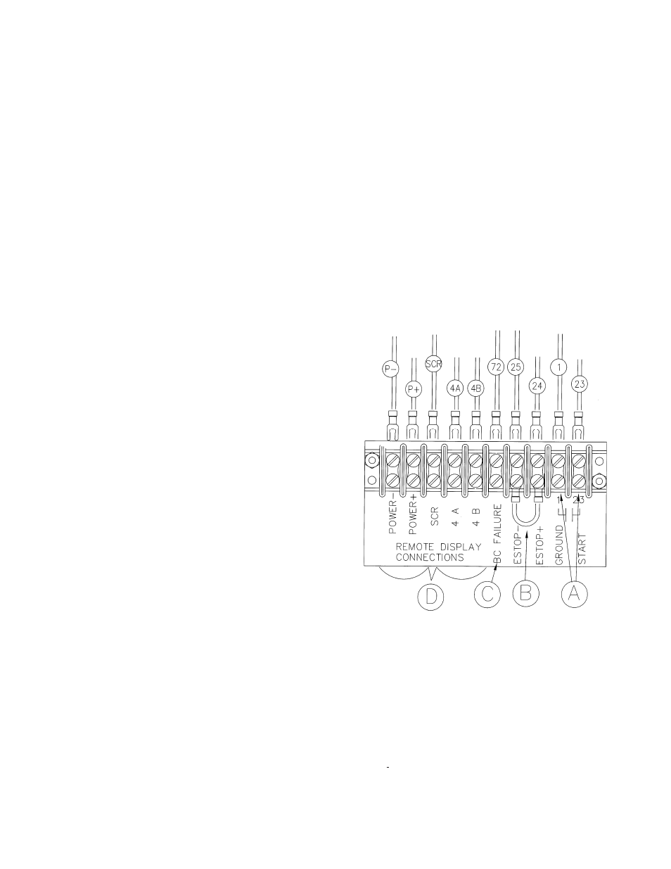
C - Ground Lug, These ground lugs are bonded to ground
and are provided for you to connect your ground wire from the
transfer switch to. The lugs on the 40 kW will handle wire sizes
#6 AWG to 50 MCM and should be torqued to 50 in. lbs. The
lugs on the 1/30 kW will accommodate #6 AWG to 50 MCM
and should be torqued to 50 in. lbs.
D. 120 Volt Terminal Block, This terminal block is provide for
the 10 volt/ 15 amp feed from customers distrubution panel for
the block heater and the trickle charger.
****************
***** WARNING *****
****************
A main line circuit breaker has been provided inside the
generator housing. During all wiring installations make sure the
breaker is in the off position and the generator operation switch
is in the off position.
****************
***** WARNING *****
****************
EQUIPMENT DAMAGE - When installing a Three Phase 240
volt system be sure you know which lead is the high voltage
“wild” leg (208 Volt line to neutral). The generator normally
carries the high voltage on the G2 lead.
The load current carrying wires (L) and (T) must be sized to
handle the maximum load current without excessive voltage
drop. By code, the wire must be heavy enough to handle the
full current rating of the main line circuit-breaker (or fuse) in the
entrance (or sub-panel) protecting the contactor switch.
All wires should be installed in rigid or flexible conduit.
(Knockouts are provided in the control box).
See the manual shipped with the Automatic Transfer Switch for
connection locations in the switch. Connections in each switch
will vary depending on the type of switch and the manufacturer.
GROUNDING
A grounding lug has been provided on the engine generator set
to grounded to earth ground if required. Check with your local
codes. Generally a 8 foot copper rod driven into the earth will
provide a proper earth ground.
D.C. ELECTRICAL
CONNECTIONS
NOTE:
There are various DC connectors on the engine that have
nothing connected to them. This was done intentionally,
these connectors are for END OF LINE TESTING and
other diagnostic tests. They are not used during normal
operations and can just be ignored.
All DC connections are completed on the terminal strip just below
the engine control cabinet.
A - Customer Remote Start CONNECTIONS TERMINALS.
The two remote start leads from the Automatic Transfer Switch
are connected to the two terminals marked 1 & 3. The wire
in terminal labeled #1 is Battery Negative and the wire in the
terminal labeled #3 is your Remote Start lead. Closing these
two leads together will signal the DSE 7310 to go into an auto-
start mode and start up the engine generator.
Depending on the distance, 14 to 16 gauge stranded wire
should be used. It is suggested that these wires be labeled S1
and S3. The terminal blocks are designed to use terminal lugs
on all wires and the screws should be torqued to 9.6 in. lbs.