10 k – Viconics S3000 Installation Manual User Manual
Page 3
3
1
2
ON
Fig.6
Wall mounted sensor
Dip switch location
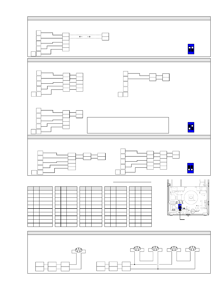
Wiring example of single remote room sensor:
Wiring examples of 2 remote room sensors for averaging applications:
Wiring examples of 3 remote room sensors for averaging applications:
Temperature vs resistance chart for 10 kOhm NTC thermistor
(R
25°C
= 10K
Ω±3% - B
25/85°C
= 3975K±1.5%)
WIRING S2000D1000, S2060A1000 and S2020E1000
Remote wiring 1 sensor Remote wiring 4 sensors
VT7600 Series thermostat VT7600 Series thermostat
ºC ºF
kohms
ºC ºF
kohms ºC ºF
kohms ºC ºF
kohms ºC ºF
kohms
-20 -4 94.5149 -10 14 54.1988 0 32 32.1910 10 50 19.7390 20 68 12.4601
-19
-2 89.2521 -9 16 51.3692
1 34 30.6120 11 52 18.8277 21 70 11.9177
-18 0 84.3147 -8 18 48.7042
2 36 29.1167 12 54 17.9636 22 72 11.4018
-17 1 79.6808 -7 19 46.1933
3 37 27.7088 13 55 17.1440 23 73 10.9112
-16 3 75.3299 -6 21 43.8268
4 39 26.3744 14 57 16.3665 24 75 10.4443
-15 5 71.2430 -5 23 41.5956
5 41 25.1119 15 59 15.6286 25 77 10.0000
-14 7 67.4028 -4 25 39.4912
6 43 23.9172 16 61 14.9280 26 79 9.5754
-13 9 63.7928 -3 27 37.5056
7 45 22.7861 17 63 14.2629 27 81 9.1711
-12 10 60.3980 -2 28 35.6316
8 46 21.7151 18 64 13.6310 28 82 8.7860
-11 12 57.2044 -1 30 33.8622
9 48 20.7004 19 66 13.0307 29 84 8.4190
10 K
10 K
10 K
10 K
10 K
Scom
MS
Scom
OS
Scom
RS
or
or
Scom
MS
Scom
OS
Scom
RS
or
or
(
AU
D1
RS
Scom
C
D2
Scom
RS
Scom
RS
C
DI
Aux
Scom
RS
Scom
RS
OR
AU
D1
RS
Scom
C
D2
Scom
RS
Scom
RS
C
DI
Aux
Scom
RS
Scom
RS
C
DI
Aux
VT7600 Series
Thermostat
1x 3020W1000
Wiring 1 sensor
S2-1 = ON / S2-2 = ON
S3010W1000
Wiring 1 sensor
S2-1 = ON / S2-2 = ON
VT7600
Series
2x S3020W1000
Wiring 2 sensors
S2-1 = OFF / S2-2 = ON
AU
D1
RS
Scom
C
D2
Scom
RS
Scom
RS
Scom
RS
Scom
RS
2x S3010W1000
Wiring 2 sensors
S2-1 = OFF / S2-2 = ON
VT7600
Series
AU
D1
RS
Scom
C
D2
Scom
RS
Scom
RS
Scom
RS
Scom
RS
C
DI
Aux
VT7600
Series
Th
t t
1x S3010W1000 and 1x S3020W1000
Wiring 2 sensors
S2-1 = OFF / S2-2 = ON
A U
D 1
R S
S c o m
C
D 2
S c o m
R S
S c o m
R S
C
D I
A u x
S c o m
R S
S c o m
R S
S c o m
R S
S c o m
R S
VT7600
Series
2x S3010W1000 and 1x S3020W1000
Wiring 3 sensors
S2-1 = OFF / S2-2 = OFF
AU
D1
RS
Scom
C
D2
Scom
RS
Scom
RS
C
DI
Aux
Scom
RS
Scom
RS
Scom
RS
Scom
RS
C
DI
Aux
VT7600 Series
Thermostat
1x S3010W1000 and 2x S3020W1000
Wiring 3 sensors
S2-1 = OFF / S2-2 = OFF
1
2
ON
Dip switch
setting for:
1 sensor
S2-1 = ON
S2-2 = ON
1
2
ON
Dip switch
setting for:
2 sensors
S2-1 = OFF
S2-2 = ON
1
2
ON
Dip switch
setting for:
3 sensors
S2-1 = OFF
S2-2 = OFF
Notes for averaging applications:
•
S3010W1000 and S3020W1000 can be mixed matched.
•
S3010W1000 and S3020W1000 are to be wired in parallel.
•
Respect the dip switch setting in each remote sensor.