Viconics S3000 Installation Manual User Manual
Page 2
2
Installation of room sensors (S3010W1000 and S3020W1000)
•
Remove security screw on the bottom of sensor cover.
•
Open up by pulling on the bottom side of sensor. (Fig.1)
Location:
1- Should
not be installed on an outside wall.
2- Must be installed away from any heat source.
3- Should not be installed near an air discharge grill.
4- Should not be affected by direct sun radiation.
5- Nothing must restrain vertical air circulation to the sensor.
Installation:
1. Remove security screw on the bottom of thermostat cover.
2. Open up by pulling on the bottom side of thermostat.
3. Pull out cables 6” out of the wall.
4. Wall surface must be flat and clean.
5. Insert cable in the central hole of the base.
6. Flip printed circuit board to access mounting hole
7. Align the base and mark the location of the two mounting holes on the wall. Install
proper side of base up.
8. Install anchors in the wall.
9. Insert screws in mounting holes on each side of the base. DO NOT
OVERTIGHTEN
10. Strip each wire 1/4 inch.
11. Insert each wire according to wiring diagram.
12. Gently push back into hole excess wring back into the wall.
13. Press back printed circuit board into place
14. Install the cover, top side
15. Install security screw.
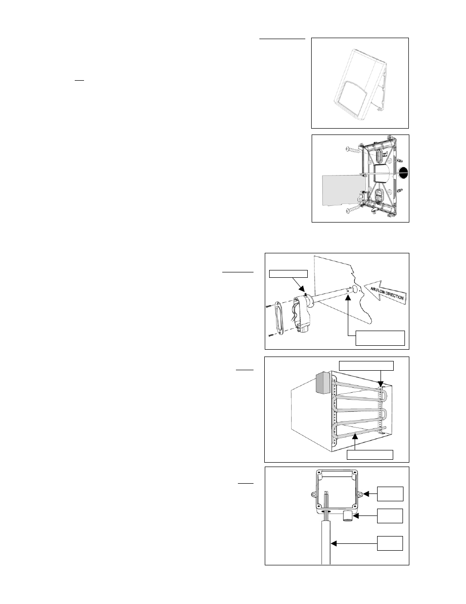
Installation of duct sensors (S2000D1000) – (Fig.3)
1. Drill 1” [25mm] hole mid height on the side of the duct to insert the
probe.
2. Loosen swivel screw and direct the probe so that the flat side of
probe tip is facing the airflow.
3. Mark the position of the two holes to be drilled for mounting the
sensor on the duct. Fasten the sensor to the duct with the two
screws provided. Do not overtighten!
4. Junction box must be directed downwards or sideways.
5. For best results, locate sensor as far as you can from
heating/cooling source.
Installation of averaging sensor (S2060A1000) - (Fig.4)
1. Drill 5/8” [16 mm] hole for the element to pass into the duct.
2. Run the sensing element into the duct.
3. Remove the cover from the unit.
4. Mark the position of the holes to be drilled for mounting the case
on the duct.
5. Fasten the sensor element in an “S” shaped pattern in order to
cover the entire duct section area. Ensure that the probe does not
touch the duct.
6. Firmly support the element in the duct using perforated steel strap
and wire fastenings.
7. For best results, locate sensor as far as you can from
heating/cooling source.
Installation of outside air sensor (S2020E1000) – (Fig.5)
1. Install sensor using mounting holes on each side.
2. Install on a vertical surface, respect mounting orientation
3. Remove the four screws and remove the cover.
4. Strip each wire 1/4 inch.
5. Insert each wire according to wiring diagram.
6. Install the cover with supplied screws.
7. In snowy area allow sufficient height for snow accumulation.
Fig. 1
Fig.4
Perforated steel
t
Sensing element
Fig. 2
Fig.5
Mounting
hole
Sensing
probe
EMT
conduit
Fig.3
Swivel screw
Probe tip, flat side
facing airflow