Viconics VBZS Application Guide User Manual
Page 32
32
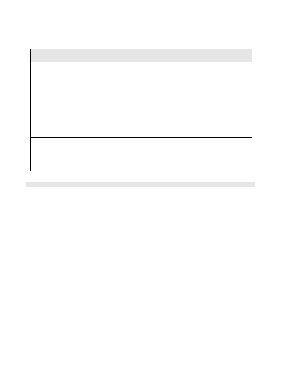
4C) Communication Status LED and Troubleshooting
Each controller has a communication status service LED for troubleshooting purposes. Monitoring this LED
will determine the network conditions for each individual device and will tell you if they are communicating
properly with other devices on the network.
Condition of the Status LED
Possible Cause
Solution
¾
1 short blink
A VZ7656 BACnet communication
module is wrongly installed on a
VZ7260 controller
Install a VZ7260 BACnet
module on the controller
A VZ7260 BACnet communication
module is wrongly installed on a
VZ7656 controller
Install a VZ7600 BACnet
module on the controller
¾
2 short blink (no network
wires connected to the
module)
The right module has been installed
on the right controller model
N/A
¾
2 short blink (network
wires connected to the
module)
Module is not at the same baud
rate as the network
Power off and on the
controller
Faulty of wrong wiring
Verify network wire
connections
¾
2 short blinks and a longer
blink (wires connected to
the module)
The module has detected the
presence of a network and is
communicating
N/A
¾
Right after power is
applied: 2 long blinks and
then no blinking
+ and - polarity has been reversed
at the module
Reverse polarity and be sure
proper polarity is respected
on the whole network
5) System Commissioning
It cannot be stressed enough that if proper system operation is expected, then proper system
commissioning should be done at all levels.
A zoning system has a huge dependency on demand and response being fully functional both at the RTU
and the zone level.
5A) Proper Commissioning of Zone Controllers
At the zone level, care should be applied to insure the following have been properly set up:
-
Proper sizing of the VAV zone damper and the design of the air distribution to insure that peak load
demands can be meet when the RTU delivers the capacity.
-
VAV Damper operation. Insure that the VAV damper blade can rotate completely. There should be
no mechanical limits as those are set by the controller parameters.
-
DA/RA setting of the VAV actuator is not set reversed, when improperly set it will result in a zone
that can never be satisfied and a demand to the RTU that will always be present if the zone is a
master zone.
-
Min, Max and HeatMax flow must be set during balancing. Also, adjustments may need to be done
to the main trunk side-take-off balancing damper if the local VAV trunk is equipped with one.
-
Proper setup of the following important configuration parameters: Reheat lockouts, setpoint limits,
user interface lockout and demand weight adjustments to the RTU. All of these need to be properly
evaluated and set according to the specifics of the installation.
-
Addressing of both the MAC zone numbers to a specific RTU controller needs to be planned prior
to the installation.