Heating / cooling valve, Heating valve cooling valve, Heating valve – Viconics VT7200 Installation Manual (Previous Release 5000 Series PIR Ready) User Manual
Page 5
5
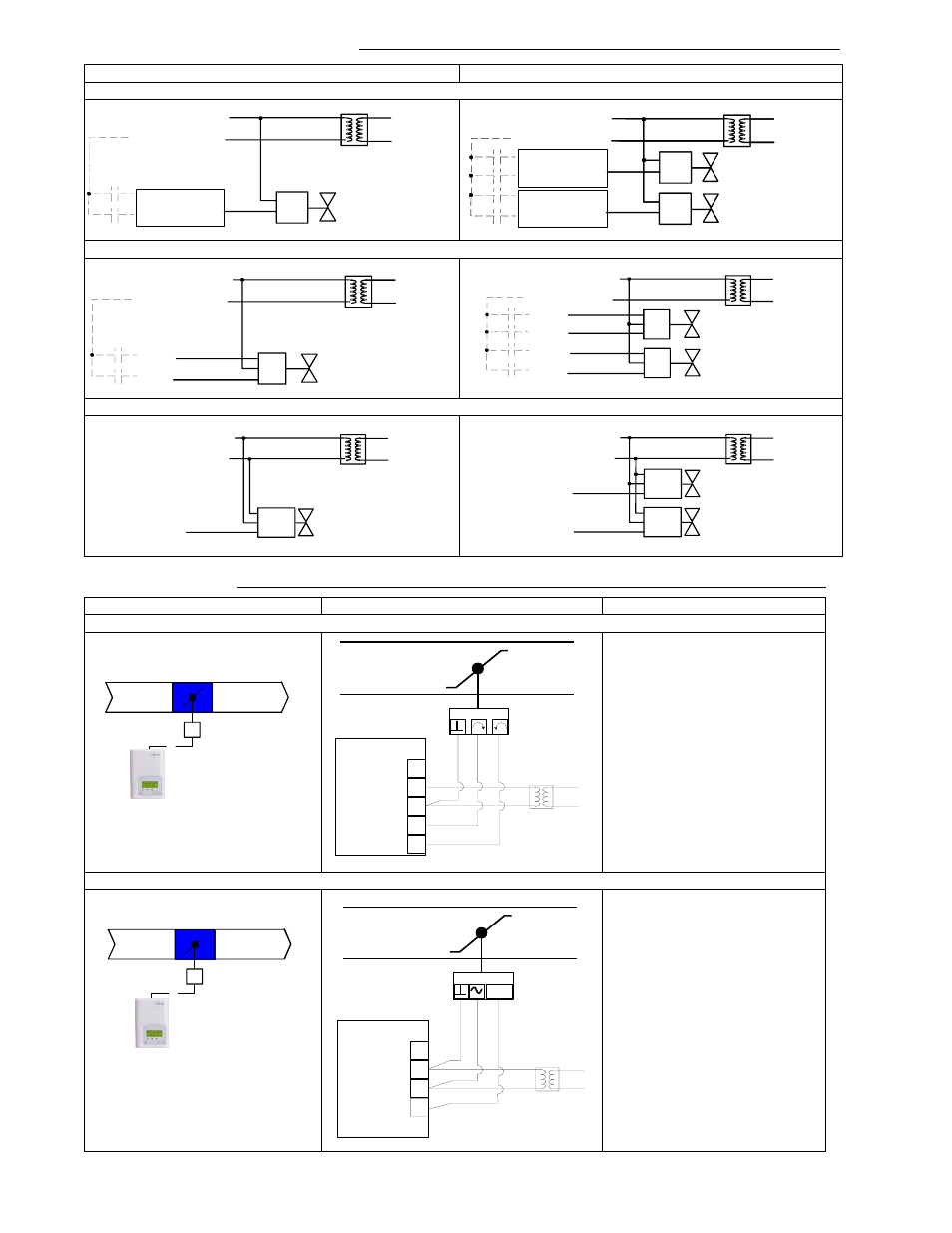
Main outputs wiring typical for valves
Single output applications
Dual output applications
On-Off control VT7200C5x00(x)
Floating control VT7200C5x00(x)
Analog control VT7200F5x00(x)
Typical applications
Schematic Wiring Settings
Pressure dependent VAV cooling only:VT7200C5x00(x) Floating actuator
Mandatory
•
Out1Conf = 2.0
•
CntrltTyp = Floating
•
FL time = as per actuator
•
SeqOpera = 0 Cooling only
Pressure dependent VAV cooling only: VT7200F5x00(x) Analog actuator
Mandatory
•
Out1Conf = 2.0
•
RA/DA = as per actuator
•
SeqOpera = 0 Cooling only
Heating / Cooling valve
24 Vac
Com
OR
24 V~ Hot
24 V~ Com
BO1
if N.O.
BO2
if N.C.
24 V~ Hot
24 V~ Com
BO3
if N.O.
BO4
if N.C.
BO1
if N.O.
BO2
if N.C.
24 Vac
Com
Heating valve
Cooling valve
24 Vac
Com
OR
OR
24 Vac
Com
Heating valve
Cooling valve
24 Vac
Com
OR
OR
Open
Com
Close
Heating / Cooling valve
24 V~ Hot
24 V~ Com
BO1
BO2
Open
Com
Close
Heating valve
Open
Com
Close
Cooling valve
24 V~ Hot
24 V~ Com
BO3
BO4
BO1
BO2
Heating / Cooling valve
Com
24 Vac
0-10 Vdc
24 V~ Hot
24 V~ Com
AO 1
24 V~ Hot
24 V~ Com
AO 2
AO 1
Com
24 Vac
0-10 Vdc
Heating valve
Cooling valve
Com
24 Vac
0-10 Vdc
Room Temperature Control
Minimum & Maximum Position
Adjusted on the actuator
Modulating Floating
VAV Actuator
UI3 COS
0 V~ Com
24 V~ Hot
BO1 Open
BO2 Close
Analog VAV Actuator
Room Temperature Control
Minimum & Maximum Position
Adjusted on the actuator
0 to 10
Vdc
UI3 COS
0 V~ Com
24 V~ Hot
AO1