Vt8300, Series controller, Remote wiring 1 sensor – Viconics VT8300 Low Voltage Installation Guide User Manual
Page 9: S2-1= on, s2-2=on, Vt8300 series installation guide, Remote sensor accessories
VT8300 Series
Installation Guide
9
Viconics Technologies Inc.
|
9245 Langelier Blvd.
|
St.-Leonard
|
Quebec
|
Canada
|
H1P 3K9
|
Tel: (514) 321-5660
|
Fax: (514) 321-4150
028-0429-02
www.viconics.com
|
February 2015
©
20
15
V
ic
onic
s T
ec
hno
lo
gi
es
Inc
. A
ll r
ig
ht
s r
ese
rv
ed
.
REmOTE SENSOR ACCESSORIES
Model no.
Description
S3010W1000
Wall mounted temperature sensor
S3020W1000
Wall mounted temperature sensor with override button and occupancy status
LED
The VT8300 room controller is compatible with remote mount temperature sensors using 10K type 2 NTC thermistors.
Note:
If one or multiple sensor(s) is/are connected into the RS terminal, the internal temperature sensor is automatically disabled. Disconnecting
the sensor(s) in the RS terminal will re-activate the internal sensor.
Features:
• Each sensor can be configured for various averaging combinations
• Optional occupancy led
• Optional override key
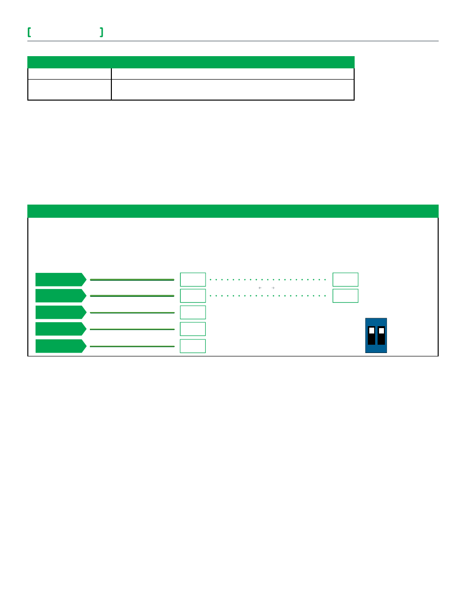
Wiring example of single remote room sensor:
Common
UI 20
BO8
24 Vac Com
UI17
VT8300
Series Controller
S3020W1000
Remote wiring 1 sensor
S2-1= On, S2-2=On
S3010W1000
Remote wiring 1 sensor
S2-1= On, S2-2=On
SCom
RS
Aux
C
DI
SCom
RS
OR
Dip switch
setting for:
1 sensor
S2-1 = ON
S2-2 = ON
ON
1 2