Vt8300 series installation guide – Viconics VT8300 Low Voltage Installation Guide User Manual
Page 8
VT8300 Series
Installation Guide
8
Viconics Technologies Inc.
|
9245 Langelier Blvd.
|
St.-Leonard
|
Quebec
|
Canada
|
H1P 3K9
|
Tel: (514) 321-5660
|
Fax: (514) 321-4150
028-0429-02
www.viconics.com
|
February 2015
©
20
15
V
ic
onic
s T
ec
hno
lo
gi
es
Inc
. A
ll r
ig
ht
s r
ese
rv
ed
.
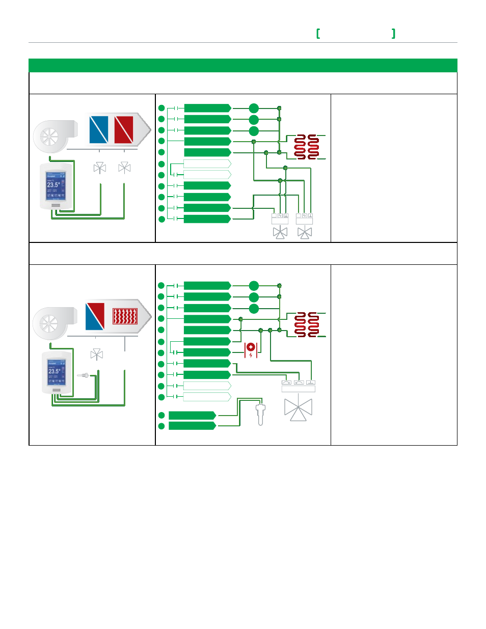
Schematic
Wiring
Settings
4 pipe system cooling and heating
Control type = Analog
Heating
Valve
3 Speed Fan
Modulating Analog
Room Temperature
Control Thermostat
Cooling
Valve
BO2 - Fan L
BO3 - Fan M
BO4 - Fan H
RC (24 Vac)
C (Common)
RH
BO8 - Aux Heat
UO9
UO10
UO11
UO12
24 Vac fan relays
24 Vac Transformer
HIGH
MED
LOW
Heating
2
3
4
5
6
7
8
9
10
11
12
Cooling
0 to 10
Vdc
0 to 10
Vdc
Mandatory
• Pipe no = 4 pipes
• CntrltTyp = Analog
• Fan Menu = 0 (L-M-H)
• RA/DA = as per actuator
• SeqOpera = 4 Cool/Heat
2 pipe system cooling or heating with reheat
Control type = Floating
Electric
Reheat
3 Speed Fan
Modulating Floationg
Room Temperature
Control Thermostat
Cooling / Heating
Valve
Sensor
BO2 - Fan L
BO3 - Fan M
BO4 - Fan H
RC (24 Vac)
C (Common)
RH
BO8 - Aux Heat
UO9
UO10
UO11
UO12
24 Vac fan relays
24 Vac Transformer
HIGH
MED
LOW
SCom
UI 19 - UI13
Optional supply water
temperature sensor
2
3
4
5
6
7
8
9
10
11
12
18
19
Electric
Reheat
Normally Closed
Mandatory
• Pipe no = 2 pipes
• CntrltTyp = Floating
• Fan Menu = 0 (L-M-H)
• FL time = as per actuator
• SeqOpera = 2 Cool/Reheat
• UI3 = COS