USL XTM-300 User Manual
Page 8
8
Features
The XTM-300 Series Crossover Module has the following standard features:
Designed to split the signals of the left, center and right channels for use with bi-amplified
sound systems.
Analog or digital crossover card for processing the left, center and right channels.
Provides input point for a spare channel that can be monitored using the USL CM-8E
monitor.
Provides an emergency bypass crossover should the main power supply fail.
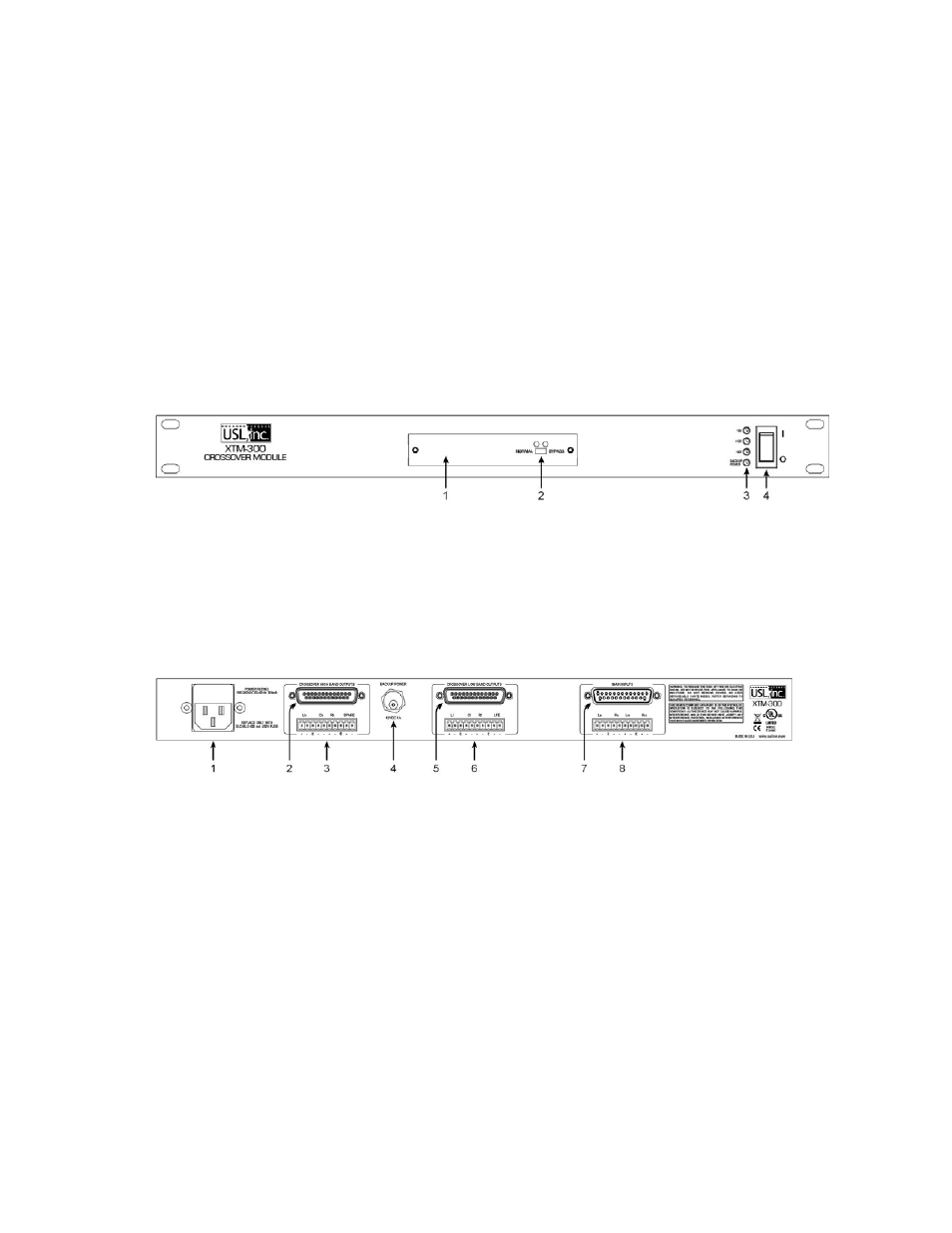
1. Crossover card access cover
.
2. Crossover bypass switch - When in bypass, the active crossover is replaced with a passive
crossover for emergency use.
3. Power Supply Voltages Status LEDs
4. Power Switch
1. Main AC connector with fuse.
2. Crossover output to monitor - L, C, R high bands and spare. (DB25 male)
3. Crossover output to monitor/amplifier - L, C, R high bands and spare input.
4. DC emergency power input - 12VDC, 1A
5. Crossover output to monitor - L, C, R low bands, Ls/Rs, Lrs/Rrs, LFE. (DB25 male)
6. Crossover output to monitor/amplifier - L, C, R low bands and LFE.
7. Main input - connect this to the main output of the processor. (DB25 female)
8. Surround outputs to monitor/amplifier - Ls/Rs, Lrs/Rrs.