Led mechanical adjustment, Led current adjustment, Focus, azimuth and ccd lateral adjustment – USL DSTR-20 Manual User Manual
Page 9: Sensor board status light circuit
DSTR-20
I
NSTRUCTION
M
ANUAL
USL/B.A.C.P.
- 8 -
LED Mechanical Adjustment
Verify correct LED position by loosening the two LED/heat sink screws and rotate
for maximum video output. Tighten screws.
LED Current Adjustment
As time passes, the LED output will diminish. Our initial LED current setting of about
140 mA should ensure years of service before the video output level drops below the
established minimum of 1.5 Volts video output. The video status light will turn from
green to red indicating it is time for a service call.
LED current can be adjusted by means of a trim pot located beneath the CCD/Lens
cover. Remove the cover and adjust the trim pot to yield 4.5 Volts video output on the
scope.
Focus, Azimuth and CCD lateral adjustment
Azimuth is adjusted by rotating the sensor PC board. When properly adjustd, the
DRAS software display should indicate an azimuth of
ø
degrees.
Focus is adjusted by loosening the lens clamp screw and turning the knurled lens nut
to adjust the lens in and out for best video resolution on the scope or DRAS.
CCD horizontal position is adjusted by loosening the PC board screws and sliding the
CCD board in and out until the DRAS perforation display is centered.
Note: In all casses, an oscilloscope is required for viewing the video output signal
during CCD focus, alignment and initial Red LED current adjustment. Re-adjust the
Red LED current if the Status Light LED displays red during an SRD film.
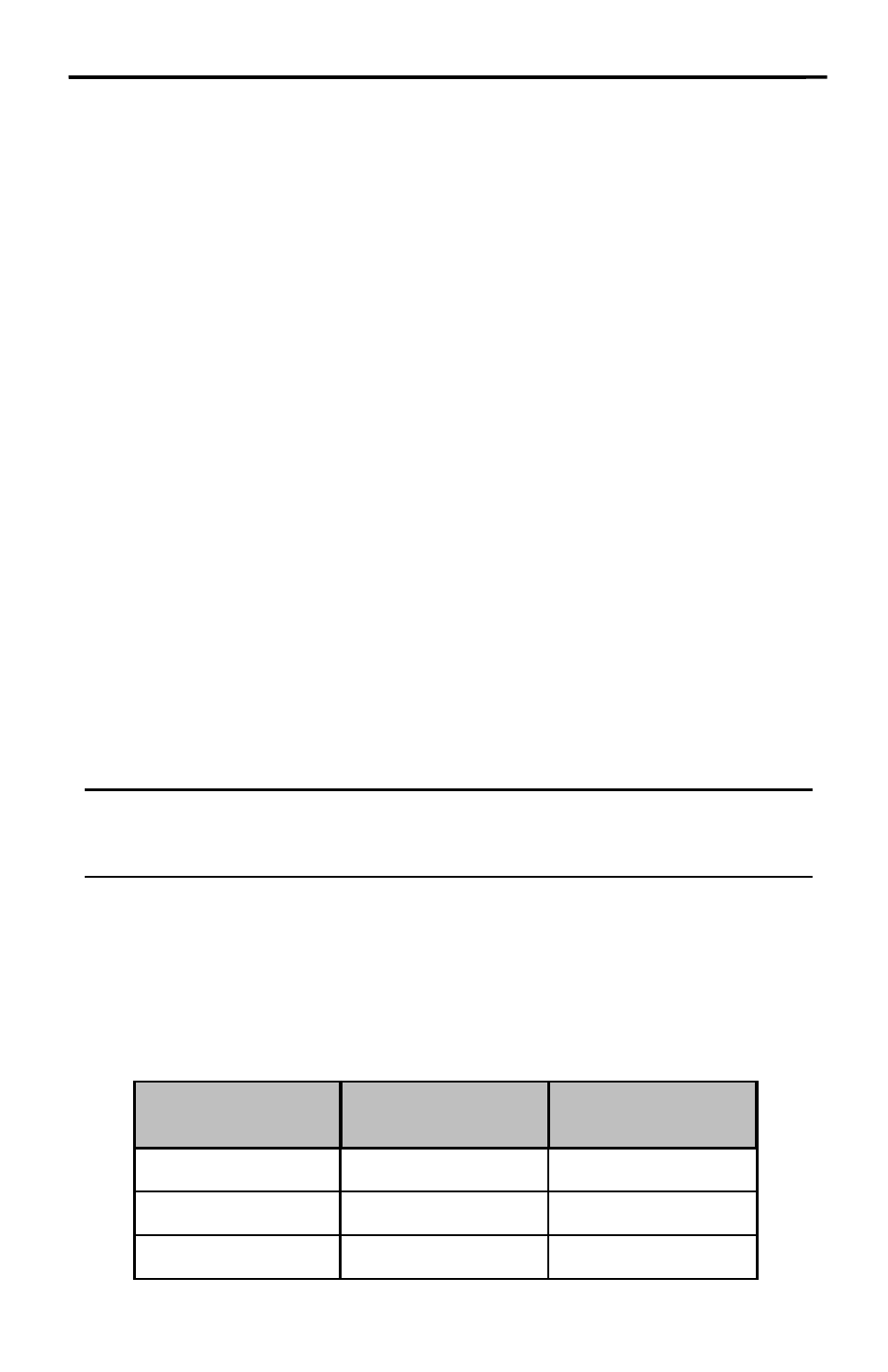
Sensor Board Status Light Circuit
After focus and alignment of the Sensor Board, running an SRD film, increase the
Red LED current until the Status Light displays yellow, and then back the current
down until the Status Light LED displays green. This is the maximum video voltage
of the normal video range.
LED color
(Status Light)
Video
Description
Video Range
Red
Low
0.0 -1.5V
Green
Normal
1.5 - 4.5V
Yellow
High
>4.5V