USL CM-8E User Manual
Page 31
31
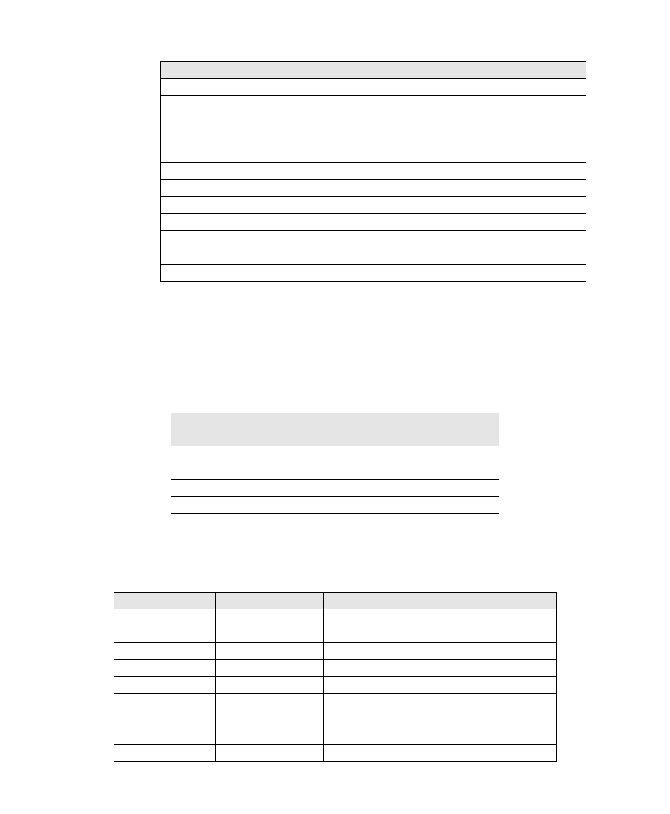
DB-25F Pin
Signal Name
Channel Name
14
L-
Left-
15
GND
16
Lrs+
Left Rear Surround+
17
C-
Center-
18
GND
19
Rrs+
Right Rear Surround+
20
R-
Right-
21
22
GND
23
Ls+
Left Surround+
24
Rs+
Right Surround+
25
LFE+
Low Frequency Effects+
Crossover and Spare Inputs
When there is a crossover before the CM-8E, this connector carries the high band audio for the
screen channels. In addition, this connector has a “spare” audio input.
Signals Listed By Channels
Audio Channel
DB-25F Crossover
Input Pins (+, -, shield)
Left High
2, 14, 1
Center High
5, 17, 4
Right High
8, 20, 7
Spare
25, 12, 13
Signals Listed By Connector Pins
DB25F Pin Out
Signal Name
Channel Name
1
GND
2
Lh+
Left High+
3
4
GND
5
Ch+
Center High+
6
7
GND
8
Rh+
Right High+
9
GND