Connection, Wall mounting – Toa RS-191 User Manual
Page 2
Printed in Japan
133-06-249-2C
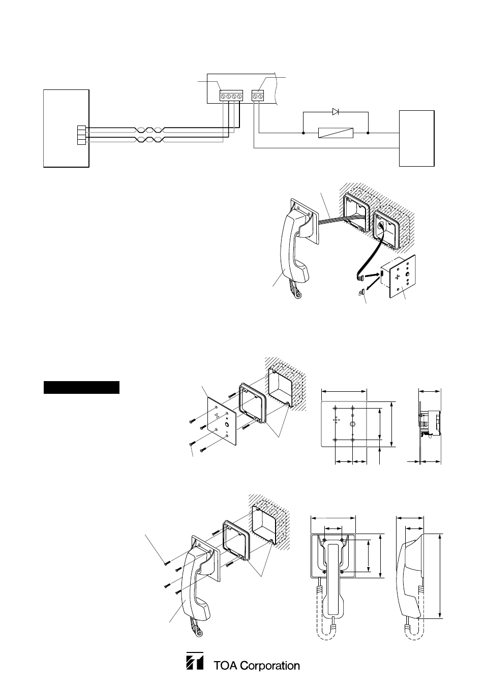
3. CONNECTION
3.1. External relay device, RS-190, and VS-910RS connection
2
1
AB
D
C
(VS-910RS)
A
B
C
D
2 twisted pair cables
CN1
CN8
Open collector output
: 24 V DC, 30 mA
External
power supply
Relay
Diode
+24 V DC
GND
+
-
RS-190's side panel
3.2. RS-190 and RS-191 connection
Plug out the jumper from the connector on the
RS-190's side panel, then plug the RS-191's
connection cable instead.
RS-190
Jumper
Connection cable
RS-191
3. WALL MOUNTING
Mount the RS-190 and the RS-191 to electrical boxes mounted in the wall.
Note: The wall should be over 12 mm thick, and the opening in the wall for an electrical box should be under
120 mm by 120 mm.
[RS-190]
[RS-191]
RS-191
46
116
70
48
83.5
115
220
Oval head combination screw
M4 x 25 (supplied with the RS-191)
[Dimensional diagram]
Unit: mm
2-gang electrical box
YC-302 (optional)
RS-190
[Dimensional diagram]
Unit: mm
46
120
58.5
37
18.2
83.5
120
2
53
2-gang electrical box
YC-302 (optional)
Oval head combination screw
M4 x 25 (supplied with the RS-190)
Accessory screws
The RS-190 and RS-191 come with
2 types of screws: oval head
combination screw M4 x 25 and oval
head slotted screw UNC No.6 x 18.
For the electrical box provided with
unified threads, use the oval head
slotted screws UNC No.6 x 18.