Beam clamp bracket j-bolt – Tie Down Concrete Foundation System User Manual
Page 2
Xi2 Lateral Stabilization with Concrete Footers
Installation of Concrete Bracket: Dry Set/Wet Set
1. Identify the number of systems to be used on the home using the
chart provided.
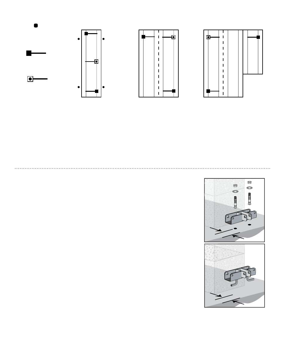
2. Identify the location where the lateral systems will be installed. If installing
lateral and longitudinal together, check page 4 for alignment of bracket.
3. Build pier according to State, Local or Home Manufacturers guidelines.
4a. For dry set: drill two 3/8”x 3” deep holes in the concrete using holes in
galvanized bracket as a guide. Attach bracket to concrete pad using
3/8”x 3-1/2” wedge anchors provided. Place nut & washer on anchor, leave
enough room for 1 to 2 threads showing on top of bolt. Using a hammer,
tap the wedge bolts into hole through bracket, leaving nut & washer flush
with bracket. Using a 9/16” socket wrench, tighten wedge/anchor bolt,
securing bracket to the concrete.
4b. For wet set: align bracket and submerge legs completely in concrete.
Bottom of bracket should rest on surface.
5. Attach the end of the smaller tube to the bracket mounted on the pad, using the
grade 5, 1/2” x 2-1/2” bolt/nut provided.
6. Attach the flag end of the larger tube to the opposite I-beam using the
“J” bolt over the top of the I-beam with the nut & washer provided.
(Figure 1 on last page)
7. Install a minimum of four (#14 x 1” Tek screws) self-tapping screws into
the holes provided in the lateral strut so that the two tubes are connected
together with a minimum overlap of 4” to 6” (Figure 2 on last page).
End of Home
End of Home
I-Beam
Lateral
Longitudinal
Beam Clamp
Bracket
J-Bolt
Nut & Washer
1-1/2" Tube
Lateral Struts
1-3/4" Tube
4 - 1#12 x 1"
Tek Screws
Lateral
I-Beam
Minimum distance from
edge: 1-1/2”, stamped
part #59264
Single Section Home
0 - 76’ Box
2 Xi2 Systems
Over 76’ Box 3 Xi2 Systems
Single Section Home
0 - 64’ Box
2 Xi2 Systems
Over 64’ Box 3 Xi2 Systems
Double Section Home
0 - 76’ Box
2 Xi2 Systems
Over 76’ Box 3 Xi2 Systems
Double Section Home
0 - 64’ Box
2 Xi2 Systems
Over 64’ Box 3 Xi2 Systems
Triple Section Home
0 - 76’ Box
2 Xi2 Systems
Over 76’ Box 3 Xi2 Systems
Triple Section Home
0 - 64’ Box
2 Xi2 Systems
Over 64’ Box 3 Xi2 Systems
Xi
System
24'
28'
32'
32' 49' 65' 82' --
30' 46' 62' 76' 80'
-- 44' 58' 73' 80'
2
3
4
5
6
wide
wide
wide
(1)
(1)
(1)
Xi2 Pier
Placement
Xi
System
24'
28'
32'
32' 49' 65' 82' --
30' 46' 62' 76' 80'
-- 44' 58' 73' 80'
2
3
4
5
6
wide
wide
wide
(1)
(1)
(1)
3rd System
for Placement
* For Wind Zone I - Approved anchor w/strap from 45 to 90 degrees, within 10’ of end of home on single sections.
NOTE: Diagram represents single section up to 16’ width, double section up to 32’ width, and triple section homes up to 48’ width.
Approved Anchor*
with strap from
45 to 90 degrees
Wind Zones
I & II
Wind Zones
III
See “Footer Requirement”
on page 1 for edge
placement