Installation information, Right wrong, Floor jois t – Tie Down Manufactured Housing Anchor User Manual
Page 10
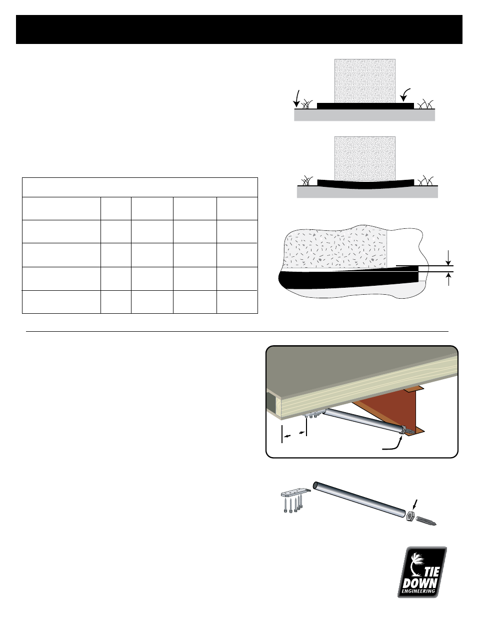
INSTALLATION INFORMATION
~ 10 ~
1. Pier spacing must be in accordance with the Home Manufacturer’s
Installation Manual and/or State or Local requirements.
2. Clear all vegetation and debris from the area where the ABS pads
are to be placed.
3. Ground under ABS pads must be leveled and evenly compacted.
4. Place ABS pad with grid side up, smooth side down. Center
blocks on ABS pad and complete pier.
Installation Instructions for ABS Pads
Pad Bearing Capacity
ABS Pad
Part#
1000 lbs.
2000 lbs.
3000 lbs.
Size
Soil
Soil
Soil
16" x 18"-
2 Sq. Ft
59300
2,000 lbs.
4,000 lbs.
6,000 lbs.
288 Sq. In.
16" x 22.5" -
2.5 Sq. Ft. 59301
2,500 lbs.
5,000 lbs.
7,500 lbs.
360 Sq. In.
17" x 25"-
3 Sq. Ft
59302
3,000 lbs.
6,000 lbs.
N/A
432 Sq. In.
24" x 24" -
4 Sq. Ft
59303
4,000 lbs.
8,000 lbs.
N/A
576 Sq. In.
Ground Level
ABS Pad
Concrete
Block
Ground Level
ABS Pad
Concrete
Block
RIGHT
WRONG
Unlevel or poorly compacted soil
Ground Level
ABS Pad
Concrete
Block
Max. 1/8”
Deflection
Deflection is measured from the highest point to the
lowest point of the top side of the pad.
Adjustable Outrigger/Diagonal Strut
Installation Instructions
1. Determine floor joist area needing support.
2. Set mounting plate on floor joist and secure with 5 (#12x2”)
screws provided. Approx. 6” from outer rim joist.
3. Insert threaded bolt in support tube and adjust so it clears
I-beam flange when mounting plate is inserted and chisel end of
bolt is placed against the frame. If support tube is too long,
simply cut square to desired length.
4. Raise floor joist with jack to desired level before tightening the
nut on the threaded bolt, snug fit to 1/4 turn past.
5. Replaces perimeter piers required for window and door support
and alignment, except as required by the home manufacturer for
larger openings.
6. For manufactured homes only, built to Federal Manufactured
Home Construction & Safety Standards.
7. The total allowable load is 864 pounds, (liveload 665 pounds),
which is the load at each side of a 46-1/2” sidewall opening in a
30 PSF roof zone for a roof tributary of 8’-6” (e.g. a 180” unit
width a 12’ eaves).
Floor Jois
t
Top Floo
r
Botto
m Flo
or
Adjustment
Locking Nut
Threaded
Bolt
6"
I-Beam
Screws
(5)
Mounting
Plate
Support
Tube
Adjustment/Locking
Nut
Threaded Bolt
Do not use on homes while being transported.
NOTE: This component is not designed or intended to replace any foundation supports required by the
home’s manufacturer and is not a repair for damaged joists.