Model 66 actuator, Model 66 actuator parts list, Parts diagram – Tie Down 66 Actuator For Serial #16020 and above User Manual
Page 4
2
4
4
1
1
6
5
8
7
8
9
11
10
1
4
3
Master Cylinder Cross Section
Dampener Cross Section
O-Ring
Wiper Seal
Piston Seal
Damper Piston
Piston Cup
Seal
Check Valve
O-Ring
Note: The check valve has been
removed in model 47211 & 86165
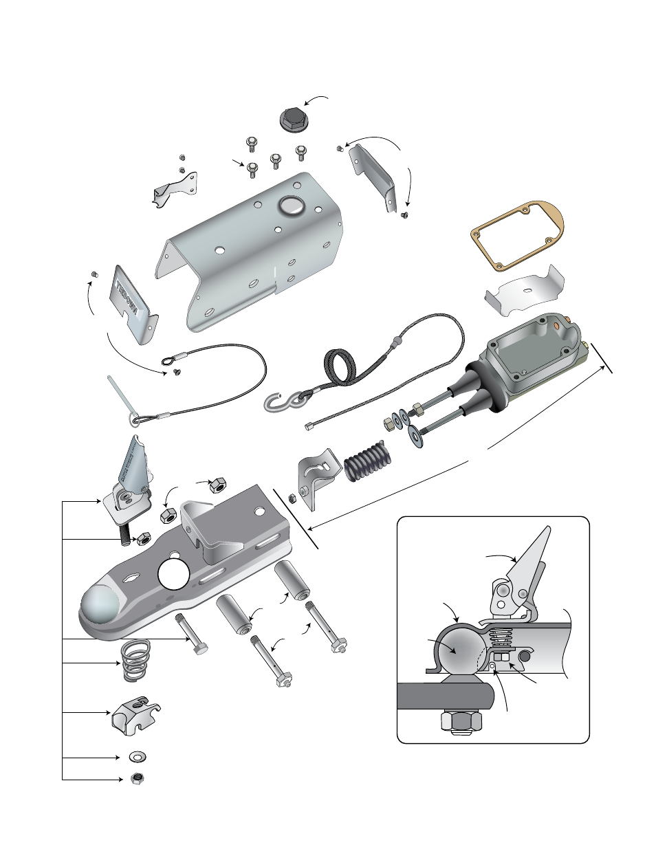
Model 66 Actuator Parts List
Model 66 Actuator
Parts Diagram
Item
Part #
Description
Quantity
1
47260 (Disc*)
Master Cylinder Assembly - Includes all nuts, baffle,
47268 (Drum)
all seals, O-rings, gaskets & seal
1
*The check valve has been removed in models 47211 & 86165
2
47261
Latch Kit Assembly
1
47262
Latch Kit Assembly (for serial #'s 16020 and below)
1
3
48801-1A
Coupler Housing
1
4
47263
Roller Kit includes:
1
1/2" X 4 Grade 5 Super Lube Bolts (2)
1/2" Hex Center Lock Nut (2)
Rollers (2)
5
50305
Cable Assembly (Breakaway) with button stop
1
50302
Cable Assembly (for serial #'s 16020 and below)
1
6
50301
Safety Pin Cable
1
7
48802
Actuator Assembly Housing
1
8
47264
Actuator Covers Kit (front & back covers & 4 Screws)
1
9
47265
Screw Kit, includes:
1
1/4" - 20NC X3/4" Hex Bolt (4)
10
48804
Master Cylinder Cap with internal bladder
1
11
48845
Safety Spring w/screws (for serial #'s 16020 and above)
1
100505,261
Tie
Down
Engineerin
g
Use Onl
y
DOT
8
Fluid
Latch
Coupler
Ball
Adjusting
Nut
Safety Lock
Hole
Note: When the coupler is placed on the ball,
the latch should close firmly. If it feels loose
or too tight, the adjustment nut should be
turned to correct the fit.