Tilt gyro module setup, Boompilot/single boom setup, Vehicle setup – TeeJet Matrix 840G Reference Guide User Manual
Page 2: Fieldpilot setup, General controls, System diagrams, Menu options, Job view, En ga ge /d ise ng ag e, Finish and ok. both are used to complete a task
www.teejet.com
www.teejet.com
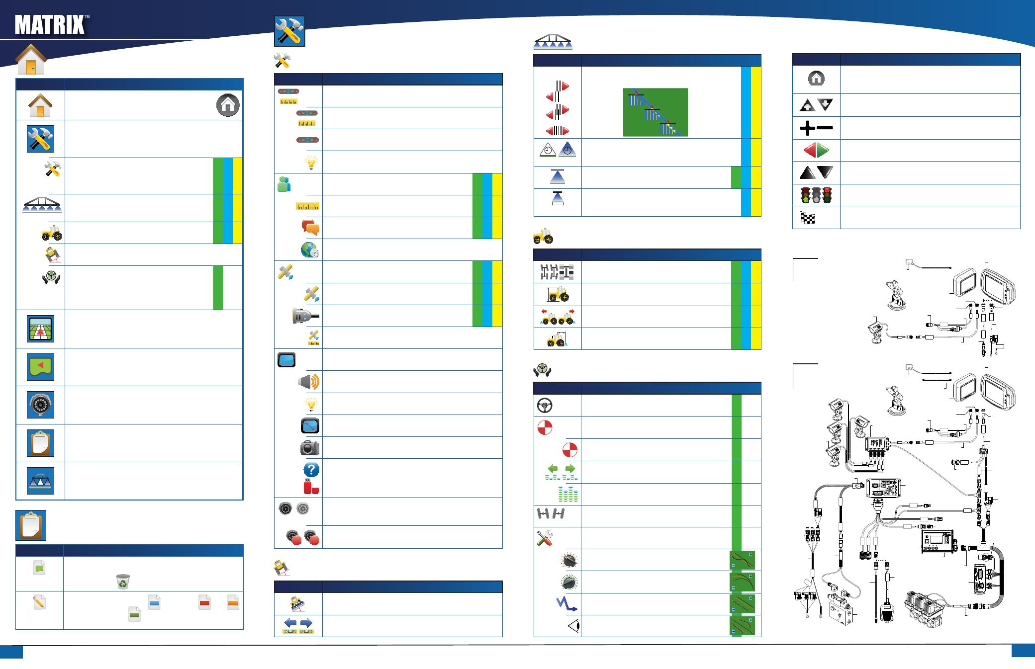
UNIT SETUP
System Setup
Icon
Description
Lightbar Setup – LED Spacing, Display Mode and
LED Brightness.
LED Spacing. Sets the distance illustrated by the
illuminated LEDs.
Display Mode. Determines whether the lightbar represents
the swath position or vehicle position.
LED Brightness. Adjusts brightness of the lightbar LEDs.
Culture Setup – Units, Language and Time Zone.
Units. Defines the system measurements.
Language. Defines the system language.
Time Zone. Establishes the local time zone.
GPS Setup – GPS Type, GPS Port and GPS Status
Information
GPS Type. Customizes system to accept GPS, DGPS, or
either type of signal.
GPS Port. Sets COM port transmission to Internal or
External.
GPS Status. Displays information regarding data rates,
number of satellites in view, and satellite quality and ID.
Console Setup – Volume, LCD Brightness, Touch
Screen Calibration, Screenshot and About/Save.
Volume. Adjusts volume level of audio speaker.
LCD Brightness. Adjusts brightness of the console display.
Touch Screen Calibration. Used to initiate a touch screen
calibration.
Screenshot. Allows screen images to be saved to a USB
drive.
About. Displays information regarding system software
as well as the software versions of modules connected to
the CAN bus.
Save. Saves console setup data to a USB drive.
Video Setup. Used to configure up to 8 cameras
with the use of a Video Selection Module. Gray =
VSM unavailable.
A
B
Cameras. Configure cameras to normal, reverse, upside
down or reverse upside down.
Tilt Gyro Module Setup
Icon
Description
Tilt Correction On/Off. Turns tilt correction on or off.
Level Tilt Positions. Calibrates Tilt Correction.
BoomPilot/Single Boom Setup
Icon
Description
Overlap. Determines the amount of overlap allowed when
the boom sections are turned on and off using BoomPilot.
0% Overlap
50% Overlap
100% Overlap
Delay Off/On. Functions as a look ahead for timing the
boom section valves to switch off or on when entering or
exiting an area that has already been applied.
#
Number of Boom Sections. Sets the number of boom
sections (1 to 15 depending on SmartCable or SDM).
Boom Section Width(s). Designates the width for the
entire swath or individual boom sections (depending on
SmartCable or SDM availability on the system).
Vehicle Setup
Icon
Description
Vehicle Type. Selects type of vehicle steering that most
closely represents your vehicle.
Antenna Height. Sets the height of the GPS antenna from
the ground.
Direction to Boom. Sets if the boom is located behind or in
front of the GPS antenna.
Boom Offset Distance. Defines the distance from GPS
Antenna to the boom.
FieldPilot Setup
Icon
Description
Autosteer. Sets FieldPilot to on or off.
Valve Setup – Valve Frequency, Minimum Duty
Cycle Left/Right and Maximum Duty Cycle.
Valve Frequency. Used to drive the steering valve.
Minimum Duty Cycle. Sets minimum amount of drive
required to begin steering vehicle left/right.
Maximum Duty Cycle. Sets the maximum speed that the
wheels will steer from left to right/right to left (lock to lock).
Valve Test Left/Right. Verifies steering is directed properly.
Used to fine tune oil flow to calibrate wheel timing.
Configure FieldPilot – Coarse Steering Adjustment, Fine
Steering Adjustment, Deadband and Look Ahead.
Coarse Steering Adjustment. Adjusts how aggressively the
vehicle maintains the guideline in Straight A-B Guidance mode.
Fine Steering Adjustment. Adjusts how aggressively the vehicle
maintains the guideline in Curved A-B Guidance mode.
Deadband. Adjusts steering if it is too choppy/responsive
or vehicle remains consistently off the guideline.
Look Ahead. Used during Straight A-B Guidance mode to
adjust the vehicle’s approach to the guideline.
General Controls
Icon
Description
Home Button. Access Home Menu options including Unit Setup,
Vehicle View, Field View, RealView Guidance, Job View and Boom
Monitoring.
Zoom In/Out Buttons. Adjust zoom settings in Vehicle View and Field
View.
Plus & Minus Icons. Used to increase or decrease a setting.
Red = Page Left or Start Test Left.
Green = Page Right or Start Test Right.
Up & Down Icons. Used to change a setting or increase or decrease
the setting.
Stop Light. Green Light = Start Testing, Red Light = Stop Testing,
Grayed = Testing off.
OK
Finish and OK. Both are used to complete a task.
SYSTEM DIAGRAMS
16-00022: Camera
C
on
ne
ct
to
+1
2v
O
nly
Powe
rC
ab
le
45-05645
Power
Cable, 12V
45-05775
10' Power
Cable, Battery
CAUTION CONN.
TO +12V ONLY
P
O
W
ER CABLE
45
-05775
DC:
XX
XX
8 Pos.
4 Pos.
8 Pos.
Speed Cable
Camera
45-05617: 20'
45-05618: 60'
Camera Extension Cable
45-05615 4 Pos.
45-05765 8 Pos.
Speed/Sense Cable
5 Pos.
+12V
32-50008
Switch
78-50155
GPS Ant.
Matrix 570G
75-30055
75-30056 w/ClearPath
Kit, RAM Mount w/Suction Cup
90-02349 (Matrix 570G)
90-02700 (Matrix 840G)
Matrix 840G
75-30070
75-30071 w/ClearPath
Matrix
FieldPilot
BoomPilot
Optional Accessory
P
O
W
E
R
IN
C
AN
RS-232
P
ow
er/
D
A
TA
45
-0
56
26
45-05626
Pwr/CAN/Data
Cable
(included with
FieldPilot and
BoomPilot kits)
3A Fuse
8 Pos.
RS-232
TJ CAN
(Terminated)
78-05077
BoomPilot
Section Driver
Module
(15 sections)
BoomPilot Harness
Part number
dependent on Rate Controller
Console Harness
Rate Controller
Remote ABSC
Status Switch
Connection
45
-0
53
81
DC: xx/x
x
Con
nect
o to
(+12
v)
45-05381
Battery 12'
w/15Amp
Fuses
CAN
Seat Sensor
Steering
Wheel Sense
GPS Power
G
P
S
In
C
O
M
1
R
em
ote
En
ga
ge
/D
ise
ng
ag
e
S
C
M
C
O
M
2
P
ow
er
S
C
M
P
ow
er
I/O
45
-0
77
03
D
C
: x
x/x
x
Va
lve
O
utp
ut
45
-1
01
03
D
C
: x
x/x
x
Steering
Valve
78-08061
Steering Control
Module (SCM)
45-07708
SCM Harness
45-10103
Harness
Steering
(A+B)
45-07703
SCM Power I/O
En
ga
ge
/
D
is
en
ga
ge
32
-0
40
20
D
C
:
xx
/x
x
32-04020
Optional
Footswitch
32-04040
Remote
Engage/
Disengage
Switch
16-00022
RealView Camera
78-08067
Module, 4CH
Video CAN
to Optional RXA GPS Antenna
45-05678
Cable, SMA-M X SMA-M
4 Pos.
8 Pos.
Speed Cable
Camera
45-05617: 20'
45-05618: 60'
Camera Extension Cable
45-05615 4 Pos.
45-05765 8 Pos.
Speed/Sense Cable
5 Pos.
+12V
32-50008
Switch
78-50155
GPS Ant.
Matrix 570G
75-30055
75-30056 w/ClearPath
Kit, RAM Mount w/Suction Cup
90-02349 (Matrix 570G)
90-02700 (Matrix 840G)
Matrix 840G
75-30070
75-30071 w/ClearPath
Matrix
FieldPilot
BoomPilot
Optional Accessory
Up to 8 cameras can be installed using 78-08068: Module, 8 Channel Video CAN.
MENU OPTIONS
Icon
Description
Home – Displays Menu Options including Unit Setup,
Vehicle View, Field View, RealView Guidance, Job View
and Boom Monitoring.
Unit Setup – Allows System, BoomPilot/Single Boom, Vehicle,
Tilt Correction and FieldPilot setups.
System Setup. Sets options for lightbar, culture (units,
language & time zone), GPS, console (volume, display
brightness, touch screen calibration, screenshot & about/
save) and video cameras.
BoomPilot/Single Boom Setup. Sets swath overlap, delay
on/off, number of boom sections and associated boom
section widths.
Vehicle Setup. Sets vehicle type, antenna height, boom
direction and boom distance from antenna.
Tilt Gyro Module Setup. Sets on/off and calibrates tilt
correction.
FieldPilot Setup. Sets autosteer on/off, options for valve
setup (frequency and minimum & maximum duty cycles),
valve testing and FieldPilot configuration (coarse steering
adjustment, fine steering adjustment, deadband & look
ahead).
Vehicle View – Allows a computer-generated image of the
vehicle position displayed in the application area. Access
options for guidance modes, boundary areas and BoomPilot.
Field View – Allows a computer-generated image of
the vehicle position and application area from an aerial
perspective. Access options for boundary areas and marked
point. Enter World View and Pan modes.
RealView Guidance – Allows a single live video input or a set
of four live inputs to be displayed instead of a computer-
generated image. Enter guidance over video and steering
angle modes.
Job View – Allows saving of information to a USB drive or
clearing of information from unit.
Boom Monitoring – Allows a computer generated view of
active/inactive boom sections. Enable/disable BoomPilot.
JOB VIEW
Icon
Description
Job Information. Gives options to clear all current job information,
bounded areas information or area counters.
Press the trash can
to delete selected information.
Save Information. Saves all data
ALL
including PDF
, KML
KML
(Google Earth) and SHP
SHP
(ESRI) files or each individual type to
USB drive.