Important information – Sure Heat VMO Vented User Manual
Page 5
BURNER SYSTEM LOCATION
1. The Burner System should be located towards the back and centered in the combustion chamber
of the vented fireplace. The Burner System should be centered from left to right, with about an
inch of space on either side.
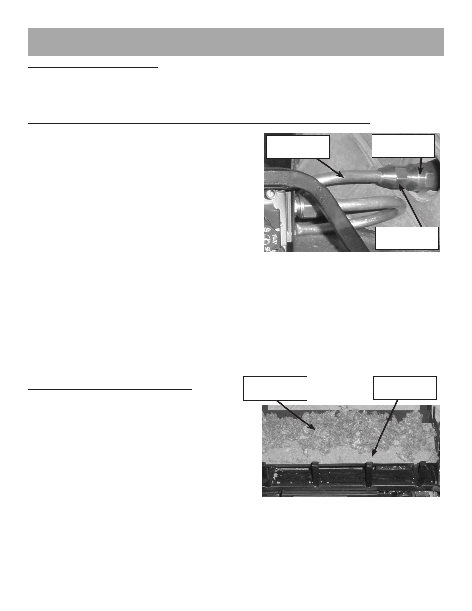
CONNECTING GAS SUPPLY TO BURNER PAN AND LOG GRATE PLACEMENT
1. Place Burner System in proper location.
2. Attach 3/8” to 1/2” gas inlet fitting to the 1/2” gas
supply stub. (See Figure 2)
3. Carefully bend the flared tubing as needed to make
the connection between the burner assembly
and the gas inlet fitting.
4. Next attach the flared tubing to the burner assembly
first, then to the gas inlet fitting.
- Avoid kinking the flared tubing while bending.
If tubing must be cut, use a tube cutter. Flare
the cut end of the tube with a flaring tube.
5. Be certain all connections are tight and use pipe compound on all male threads to seal joints.
NOTE: The pipe compound must be resistant to the action of L.P. gas. Test all connections with
a soapy water solution with gas supply turned on. If bubbles appear on any connection, retighten
and reset. Once it is determined there are no leaks whatsoever, turn off gas supply and move to
next assembly step.
GRANULE AND EMBER PLACEMENT
A. Spread granules over the installed burner pan.
Granules should not fill up the entire pan. The
granules should stop 3/4” - 1” from the top of the
pan. Slope the Granules down toward the front
of the pan without overflowing them over the
front lip of the burner pan. (See Figure 3)
B. Spread glowing embers over the top of the
granules, covering the entire surface area,
concentrating on the front and sides of the
burner pan for the most realistic burning effect.
(See Figure 3)
IMPORTANT INFORMATION
Gas Supply
Stub
Gas Inlet
Fitting
Flared
Tubing
Figure 2
Figure 3
Glowing
Embers
Granules
Page 5