Installation, Led indicators, Preparing your site – StarTech.com AP150WN1X1OG User Manual
Page 8
Instruction Manual
4
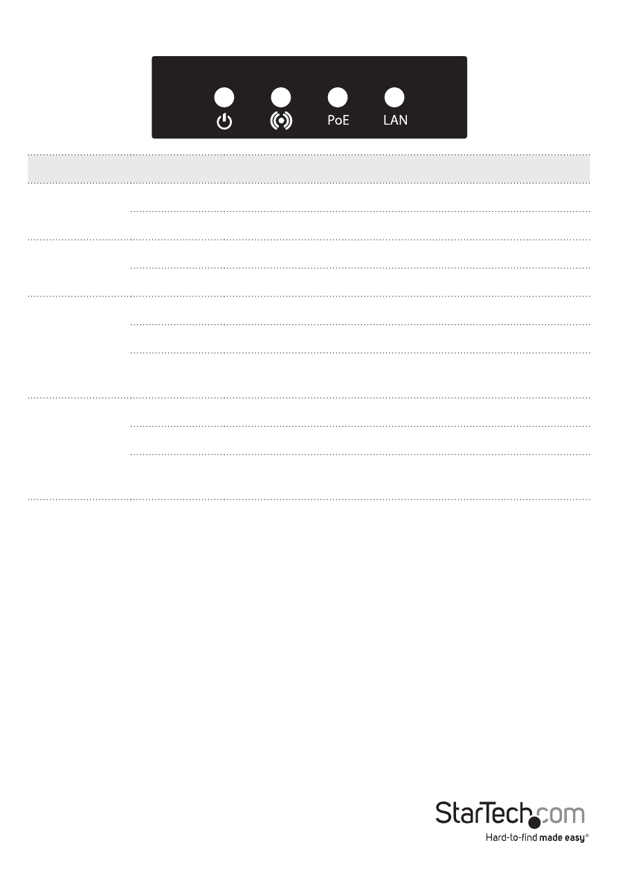
Indicator
State
Description
PWR
ON
The device is powered on
Off
The device is powered off
Wifi activity
Flashing
Data is being transmitted / received over wireless
Off
No link detected
PoE
ON
Link detected
Off
No link detected
Flashing
Data is being transmitted / received on the PoE LAN
interface
LAN
ON
Link detected
Off
No link detected
Flashing
Data is being transmitted / received on the Secondary
LAN interface
LED Indicators
Installation
Preparing Your Site
1. Determine the location for the included PoE injector and mount using the
appropriate screws/anchors for the material you are mounting to (not included).
2. Determine the location for the Wireless AP. If you are pole-mounting the AP, use
the included clamp to secure the device. If you are wall mounting the AP, use the
appropriate screws/anchors for the material you are mounting to (not included).
3. Prepare/purchase the required length of Ethernet cabling to go from the PoE
Injector to your LAN Switch or router, and from PoE Injector to the AP.
Note: The total length of Ethernet cabling from the Wireless AP to your LAN switch or
router should not exceed 100m.