Sentinel, Figure 4 – Slant/Fin SE-245 User Manual
Page 7
7
Sentinel
ELECTRICAL WIRING
DANGER:
Before wiring, always turn off electric power supply,
otherwise shock or death can result.
1. Power Supply
A separately fused circuit is recommended. Use a standard
15 Amp. fuse or breaker and 14 gauge conductors in BX
cable or circuit.
Provide disconnect means and overload protection as
required. See boiler wiring diagram (Figure 4).
Boiler must be electrically grounded in accordance with
requirements of the authority having jurisdiction, or, in the
absence of such requirements, with the National Electrical
Code, ANSI/NFPA 70-latest edition.
2. Power Connection
Connect hot and neutral to L1 and L2 terminal of the boiler
control (See figure 4).
Connect ground wire to ground screw inside boiler control.
3. Thermostat Connections
Thermostat connections must be to T and TV screw
terminals of boiler temperature control (See Figure 4).
Thermostat Heat Anticipator Adjustments
If the 24v room thermostat that controls this boiler has an
adjustable heat anticipator, connect entire system to
thermostat and run the system while measuring the current
drawn through the thermostat wires. Set the heat
anticipator at the value measured. The set current should
match power requirements by zone valves and relays.
Add an additional 0.1 Amp to the measured currrent for vent
damper. Refer to the manufacturer’s instruction of zone
valve, vent damper and relays. Also, see instructions with
the thermostat.
4. Multi Zoning
For pump zoning system, see Figures 5 and 6, for zone
valve system, see Figure 7. DO NOT use control transformer
to power external accessories like zone valve and relays,
overload and/or burned-out transformer and boiler
malfunction can result.
5. Indirect External Water Heater
If system includes indirect water heater, the indirect signal
must be separated from heating zones(s) system. See figure
6 and 8. Follow steps below:
a. Connect end switch of the indirect water heater relay
to I1 and !2 of the boiler temperature control.
b. Connect end switch of the heating zones(s) relays to
T and TV of the boiler temperature control.
c. Power DHW and heating zone(s) circulators through end
switch relays as sgown on figure 6. Do not connect
heating zone(s) circulators to C1 and C2 of the control.
Note: For single heating zone with external indirect water
heaters, see figure 9.
CAUTION:
LABEL ALL WIRE PRIOR TO DISCONNCTION WHEN SERVICING CONTROLS.
WIRING ERRORS CAN CAUSE IMPROPER AND DANGEROUS OPERATION.
"VERIFY PROPER OPERATION AFTER SERVICING".
: PROVIDE DISCONNECT MEANS AND
OVERLOAD PROTECTION AS REQUIRED
IF ANY OF THE ORIGINAL WIRE AS SUPPLIED
WITH THE APPLIANCE MUST BE REPLACED.
IT MUST BE REPLACED WITH TYP 105` OR
ITS EQUIVALENT.
IGNITER CABLE
PILOT GAS PIPE
ELECTRIC
IGNITION
PILOT
CIRCULATOR
BLOCKED VENT
SAFETY SWITCH
ROLL-OUT
SWITCH
L2
L1
C1
C2
B1
IGNITION MODULE
24V(GND)
24V
I2
B2
VENT DAMPER
HARNESS
I1
WIRE LEGEND:
FACTORY WIRED
FIELD WIRED, FIELD SUPPLIED
I
MV-PV
MV
GND
PV
MV/PV
MV
GAS VALVE
GND
(BURNER)
PV
ECONOMY
HI TEMP
Z
T
TV
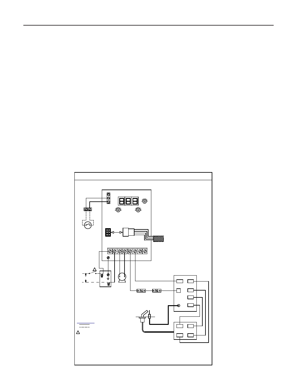
WIRING DIAGRAM FOR SENTRY & SENTINEL BOILERS WITH VESTIBULE
HYDROLEVEL HYDROSTAT CONTROL
MODEL 3200
PLUG
LO TEMP
24V
THERMOSTAT
NEUTRAL
120V/60Hz
HOT
JUNCTION
BOX
I
46 1115 000
RED
WHITE
BLK
BLUE
B
L
A
C
K
W
H
IT
E
B
L
A
C
K
G
R
E
E
N
GREEN
RED
W
H
IT
E
RED
RED
YELLOW
YELLOW
Figure 4