Base address address disable, Figure 1: idp-acb cabinet – SilentKnight SK-Zone-6 Addressable Six Zone Interface Module User Manual
Page 2
SK-460-008
2
I56-3441-000
COMPATIBILITy REQUIREMENTS
To ensure proper operation, this module shall be connected to a compatible
Silent Knight system control panel (list available from Silent Knight).
COMPONENTS
The following is a description of the SK-Zone-6 mounting framework:
One or two SK-Zone-6 modules can be installed in a IDP-ACB cabinet
•
The IDP-ACB cabinet has a built-in chassis that will accommodate one or two
SK-Zone-6 modules. For cabinet dimensions refer to the IDP-ACB instruction
manual.
The front SK-Zone-6 module positions of each chassis are offset below the rear
SK-Zone-6 module positions so that all of the status indicators are visible.
INSTALLATION STEPS
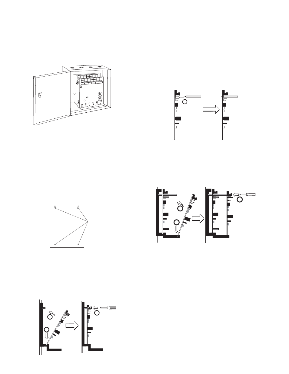
1. Cabinet Mounting
In a clean, dry area, mount the backbox using the four holes provided
•
in the back surface of the cabinet (Figure 2).
0
1
2 3 4 5 6
7
8
9
0
7
8
6
5
4
3
2
1
9
10
11
12
13
14
15
BASE
ADDRESS
ADDRESS
DISABLE
0
1
2 3 4 5 6
7
8
9
0
7
8
6
5
4
3
2
1
9
BASE
ADDRESS
ADDRESS
DISABLE
10
11
12
13
14
15
C0234-05
FIGURE 1: IDP-ACB CABINET
BACKBOX
MOUNTING
HOLES
C0235-00
FIGURE 2: TyPICAL MOUNTING hOLE LOCATIONS
2. Module Installation
There are two methods for installing a module in the rear position
of a chassis. Method one is for installation of a rear module only,
when no module will be installed in front of it. Refer to Figure 3 for
instructions. Method two is for installation of a rear module when
another module will be installed in the chassis position in front of
it. Refer to Figures 4a and 4b for method two. All necessary screws
and standoffs are supplied with the modules.
2
3
1
C0237-00
C0225-00
FIGURE 3: INSTALLATION OF REAR MODULE ONLy, METhOD ONE
Step 1:
Insert the bottom of the SK-Zone-6 module down into a rear slot on
the chassis.
Step 2: Carefully swing the upper edge of the board back towards the back of
the chassis until it touches the two standoffs.
Step 3: Align two 4-40 screws with the two standoffs and tighten.
Step 4: Address and wire the modules according to the instructions in this
manual.
The steps in Figures 4a and 4b describe and illustrate module installation
when the rear chassis position and the position in front of it will be filled.
Front position installation is possible only if the rear position is filled with a
module.
1
FIGURE 4A: INSTALLATION OF SK-ZONE-6 MODULE IN A REAR ChAS-
SIS POSITION, METhOD TwO
Step 1: Insert the bottom edge of the SK-Zone-6 module down into a rear slot
of the chassis.
Step 2: Carefully swing the upper edge of the board towards the back of the
chassis until it touches the short standoff attached to the chassis.
Step 3: Align the long standoff with the short standoff and tighten.
2
3
1
C0225-00
FIGURE 4B: INSTALLATION OF SK-ZONE-6 MODULE IN FRONT
ChASSIS POSITION
Step 1: Insert the bottom edge of the SK-Zone-6 module down into a front
slot of the chassis.
Step 2: Carefully
swing
the
upper
edge
of
the
board
towards the back of the chassis until it touches the 11/4˝ (31.75mm)
standoffs installed on the rear module.
Step 3: Align two 4-40 screws with the two standoffs and tighten.
Step 4: Address and wire the modules according to the instructions in this
manual.
wIRING
NOTE: All wiring must conform to applicable local codes, ordinances, and
regulations.
1. Install module wiring in accordance with the job drawings and appropri-
ate wiring diagrams.
2. All wiring to the SK-Zone-6 is done via terminal blocks. In order to prop-
erly make electrical connections strip approximately 1/4˝ of insulation
from the end of wire, sliding the bare end of the wire under the clamping
plate screw.
3. Set the address on the modules per the job drawing. Use the rotary code
switches to set the address of the first module between 01 and 94 (or 01
and 154 for panels that support 159 addresses).