SilentKnight ISO-6 - Six Fault Isolator Module User Manual
Page 3
INSTALLATION STEPS
1. Cabinet Mounting
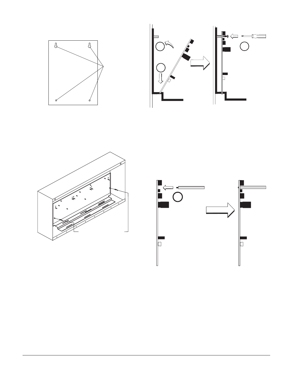
FIGURE 3: TYPICAL MOUNTING HOLE LOCATIONS
BACKBOX
MOUNTING
HOLES
In a clean, dry area, mount the backbox using the four holes provided in the
back surface of the cabinet.
2. Chassis Installation
The CH-6 chassis is mounted in the BB-6 cabinet. It is shipped with two self-
threading screws, which are used to fasten the chassis to the back wall of the
cabinet (see Figure 4).
FIGURE 4: MOUNTING THE CH-6 CHASSIS
MOUNT WITH
SELF-THREADING SCREWS
TO BACK OF CABINET
The BB-2 cabinet comes with the chassis already installed, so no mounting
is necessary.
3. Module Installation
There are two methods for installing a module in the rear position of a chas-
sis. Method one is for installation of a rear module only, when no module will
be installed in front of it. Refer to Figure 5 for instructions. Method two is for
installation of a rear module when another module will be installed in the
chassis position in front of it. Refer to Figures 6a and 6b for method two. All
necessary screws and standoffs are supplied with the modules.
FIGURE 5: INSTALLATION OF REAR MODULE ONLY, METHOD ONE
2
1
3
Step 1: Insert the bottom of the ISO-6 module down into a rear slot on the
chassis.
Step 2: Carefully swing the upper edge of the board back towards the back of
the chassis until it touches the two standoffs.
Step 3: Align two 4-40 screws with the two standoffs and tighten.
Step 4: Wire the modules according to the instructions in this manual.
The steps in Figures 6a and 6b describe and illustrate module installation
when the rear chassis position and the position in front of it will be filled.
Front position installation is possible only if the rear position is filled with an
input/output module.
FIGURE 6A: INSTALLATION OF ISO-6 MODULE IN A REAR CHASSIS
POSITION, METHOD TWO
1
Step 1: Insert the bottom edge of the ISO-6 module down into a rear slot of
the chassis.
Step 2: Carefully swing the upper edge of the board towards the back of the
chassis until it touches the short standoff attached to the chassis.
Step 3: Align the long standoff with the short standoff and tighten.
2 I56-4096-000
C0235-00
C0236-00
C0243-00
C0244-00