SilentKnight ISO-6 - Six Fault Isolator Module User Manual
Page 2
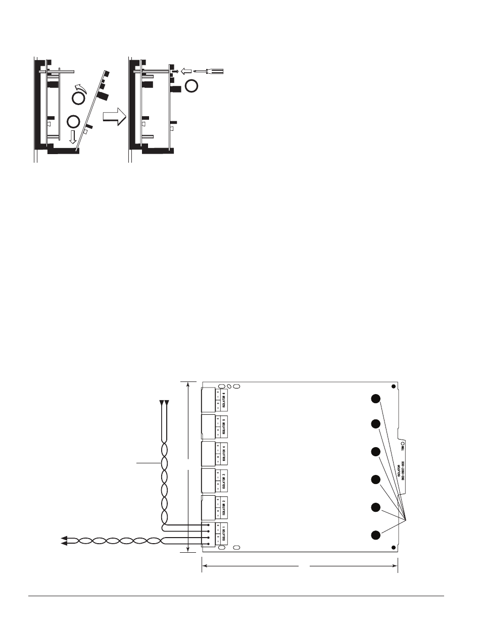
FIGURE 6B: INSTALLATION OF ISO-6 MODULE IN FRONT CHASSIS
POSITION
2
1
3
Step 1: Insert the bottom edge of the ISO-6 module down into a front slot of
the chassis.
Step 2: Carefully swing the upper edge of the board towards the back of the
chassis until it touches the 1
1
/
4
˝ (31.75mm) standoffs installed on the
rear module.
Step 3: Align two 4-40 screws with the two standoffs and tighten.
Step 4: Wire the modules according to the instructions in this manual.
WIRING
NOTE: All wiring must conform to applicable local codes, ordinances, and
regulations.
1. Install module wiring in accordance with the job drawings and appropri-
ate wiring diagrams.
2. Make electrical connections by stripping approximately
1
/
4
˝ (6.35mm) of
insulation from the end of the wire sliding the bare end of the wire under
the clamping plate, and tightening the clamping plate screw.
NOTE: All references to power limited represent “Power Limited (Class 2)”.
3 I56-4096-000
C0245-00
6.8"
5.8"
FROM PANEL
OR PREVIOUS DEVICE
SIGNAL LINE CIRCUIT
32 VDC MAX.
TWISTED PAIR
IS RECOMMENDED
TO NEXT
DEVICE
–
+
–
+
–
+
STATUS
INDICATORS
FIGURE 7: WIRING AND PROGRAMMING THE ISO-6 MODULE
C0205-05