SilentKnight 5865-3/5865-4 Remote LED Annunciator User Manual
Silent knight, Specifications
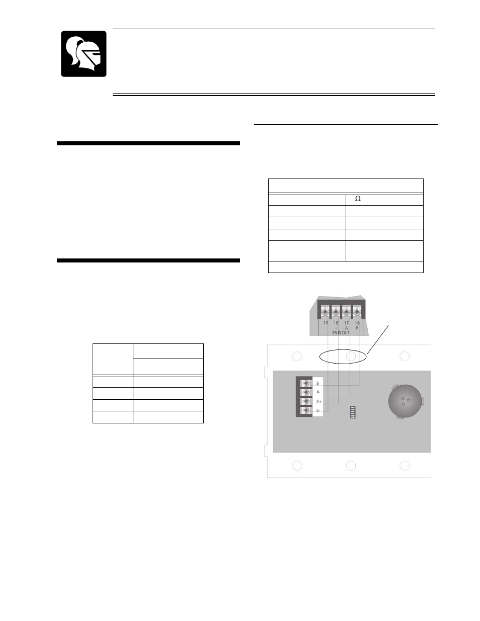
Table of contents
Document Outline
- 5865-3 and 5865-4 Installation Instructions
- Wiring the 5865-3 or 5865-4
- B
- B
- A
- A
- S+
- +
- S-
- -
- Max. Line Resistance
- 50W
- Max. Alarm Current
- 145 mA
- Standby Current
- 35 mA
- Max. Voltage
- 24 VDC
- Operating Temperature
- 0° to 49° C (32° to 120° F)
- Indoor Use Only
- Figure 1 : 5865-3 or 5864-4 Connection to the FACP
- Setting the Device Address
- Mounting the 5865-3
- 1. Make sure that the 5865-3 is properly wired to the control panel. See Figure 1.
- 2. Place the 5865-3 into the 3-gang electrical box. See Figure 3.
- 3. Place cover plate over the top of the 5865-3 and align the holes. See Figure 3.
- 4. Insert the six cover plate screws into six screw holes on the 3-gang electrical box.
- 5. Screw the six cover plate screws all the way in until the cover plate fits firmly against the 5865-3 and the electrical box. Do Not over tighten.
- Mounting the 5865-4