Setting the device address, Figure 2 : setting the device address, Mounting the 5865-3 – SilentKnight 5865-3/5865-4 Remote LED Annunciator User Manual
Page 2: Figure 3 : 5865-3 mounting, Mounting the 5865-4
Models 5865-3 and 5865-4 Installation Instructions
P/N 151088 Rev C
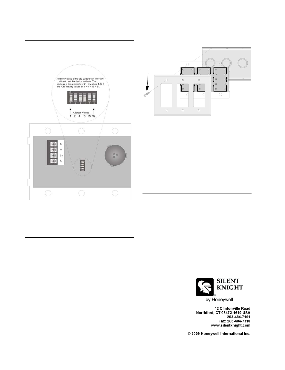
Setting the Device Address
Refer to Figure 2 to set the DIP switches to the
desired address.
Figure 2: Setting the Device Address
Mounting the 5865-3
The 5865-3 mounts into a standard 3-gang
electrical box.
Follow these steps to mount the 5864-3:
1. Make sure that the 5865-3 is properly wired
to the control panel. See Figure 1.
2. Place the 5865-3 into the 3-gang electrical
Cover Plate
5865-3
3-gang
Electrical Box
Cover
Plate
Screw
Figure 3: 5865-3 Mounting
3. Place cover plate over the top of the 5865-3
and align the holes. See Figure 3.
4. Insert the six cover plate screws into six
screw holes on the 3-gang electrical box.
5. Screw the six cover plate screws all the way
in until the cover plate fits firmly against the
5865-3 and the electrical box. Do Not over
tighten.
Mounting the 5865-4
The 5865-4 mounts into a standard 4-gang
electrical box.
Use the same procedure as used for mounting
the 5865-3.
Note: The 5865-4 uses 8 cover plate screws.