Control panel overview – Shellab SCO10A-2 User Manual
Page 8
8
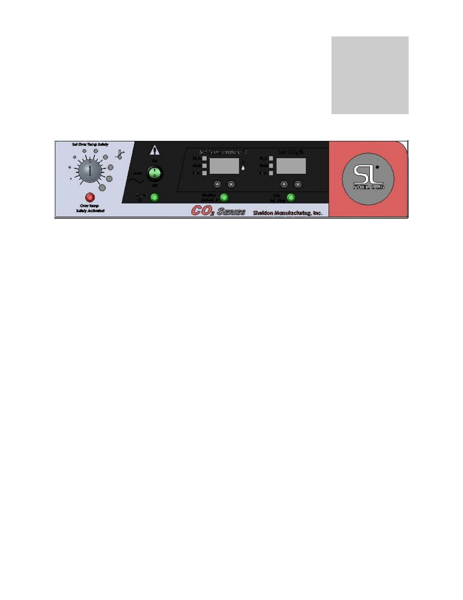
CONTROL PANEL OVERVIEW
(See Figure 1)
Figure 1
All controls are located on the front panel. Units with a detachable cord have a fused inlet located
at the top rear of the incubator. This inlet has a recessed male plug, fuse and an EMI filtering
system designed to filter out electrical interference. This inlet also prevents any internally
generated interference from feeding out to the power grid.
4.1 Power Switch: The I/O (ON/OFF) switch controls all of the power for the incubator and must be in
the I/ON position before any systems are operational. Both temperature and CO
2
displays will
illuminate when the power switch is in the ON position.
4.2 Safety Activated Light: This pilot lamp is on whenever the Over Temperature Safety thermostat
has been activated and taken control of the heating element. During normal operating conditions this
indicator should never be on.
4.3 Temperature Control: This controller is marked C
and indicates the actual temperature within the
chamber to .1
C. The UP/DOWN buttons are used for imputing the set point, calibrating the display,
and muting or unmuting the audible alarm. The HIGH and LOW alarm indicators will light whenever
there is an alarm condition associated with the temperature within the chamber. The MUTE indicator
will light whenever the audible alarm has been deactivated.
4.4 CO
2
Control: This controller is marked %CO
2
and indicates the %CO
2
content within the chamber
to .1%. The UP/DOWN buttons are used for to input the set point, calibrating the display, and muting
or unmuting the audible alarm. The HIGH and LOW alarm indicators will light whenever there is an
alarm condition associated with the CO
2
% within the chamber. The MUTE indicator will light
whenever the audible alarm has been deactivated. The CO
2
injecting light will illuminate whenever
the controller is injecting CO
2
into the chamber.
4.5 Over Temperature Safety Control (OTP): This is a hydraulic thermostat that is wired between the
Main Temperature Controller and the heating element and functions as an override control. If at any
time the Temperature Control fails in the ON position, and the temperature in the incubator rises
above its set point, the OTP is activated and maintains temperature at its own set point. Note that
the HEATING indicator will continue to function under the control of the Over Temperature Safety.
4.6 CO
2
Sample Chamber: This is located in the upper front corner of the right side of the incubator.
A sample can be drawn to measure the CO
2
content in the chamber at this port.
Muting Audible Alarms: The audible alarms can be muted for a single alarm occurrence by pressing
and holding down EITHER the UP or DOWN button for several seconds until the alarm mutes. There is a
built in delay of approximately 15 minutes on the occurrence of a LOW alarm. This time delay prevents
the audible alarm from activating when not needed.
Section
4