Installation (cont’d) – SeaLand VHT 4500 Holding Tank - 140 Series VacuFlush Toilet User Manual
Page 8
8
insTallaTion (cont’d)
ElEcTRical sYsTEM
Electrical installation must
follow abYc standards and
be performed by qualified
personnel only!
VacuuM PuMP
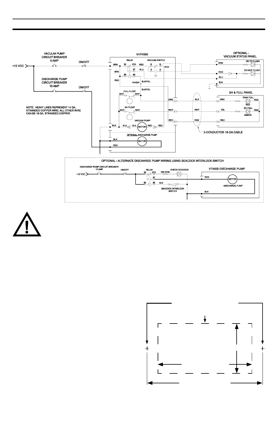
Vacuum pump must be protected by a
5-amp
fuse or circuit breaker. Connect wires
according to wiring diagram.
TanK lEVEl PRobEs
“3/4 FULL” and “FULL” tank level probes are
pre-installed in the vacuum holding tank.
Connect wires to the TankWatch Status Panel
according to the wiring diagram.
DischaRGE PuMP (VhT4511)
Discharge pump must be protected by a
10-amp fuse or circuit breaker. Fuse or circuit
breaker for discharge pump must be on circuit
that is separate from toilet electrical circuit.
Connect wires according to wiring diagram.
TanKWaTch sTaTus PanEl
1. Select a location for the holding tank status
panel. Make sure that wires from tank level
probes and status panel can be connected
with panel in chosen location.
2. Cut an access hole in the wall according to
template (below).
3. Connect wires from panel to probe wires
according to wiring diagram (supplied sepa-
rately).
4. Fasten panel to wall with two fasteners that
are provided.
1-7/8 in. (48mm)
1 in. (25mm)
2-9/32 in. (58mm)
TankWatch Panel Mounting Template
(actual size)
LIGHT/WIRING ACCESS HOLE
FASTENER LOCATIONS
Wiring Diagram