Reznor VR Option - Option - Installation - Side Shield User Manual
Page 3
Form I-VR-S, P/N 205742 R4, Page 2
Installation
Instructions (cont’d)
www.RezSpec.com
(800) 695-1901
©2012 Thomas & Betts Corporation, All rights reserved.
Trademark Note: Reznor
®
is registered in at least the United States.
11/12 Form I-VR-S (Version D)
2) Starting at the already installed retainer wire at the burner box (or wherever the
side shield is being placed), determine where an additional wire retainer is needed
for the slot cut in the other end of the 60-3/4” long side shield. At that location,
install a tube bracket and wire retainer supplied with the side shield. (See
FIGURE
2.) (NOTE: Suspension is not required at the additional wire retainers installed to
support side shields.)
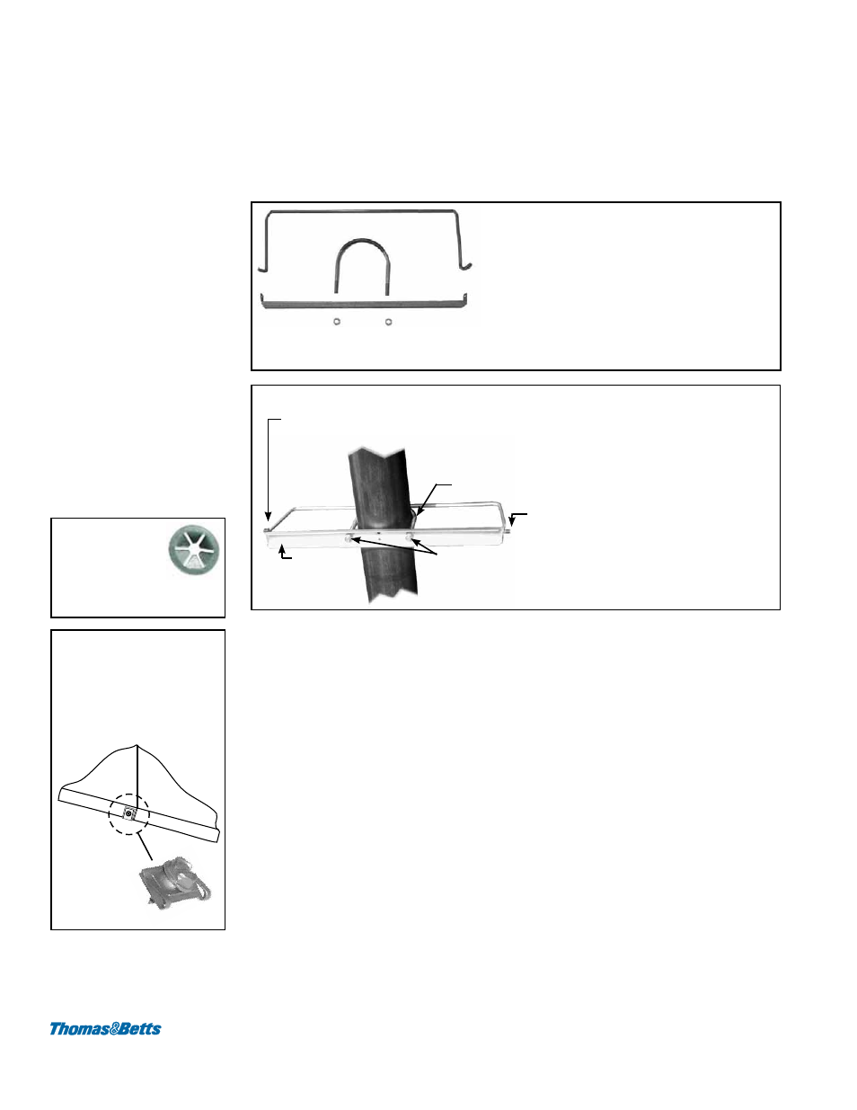
Install the tube bracket and wire retainer at the determined location (See
FIGURES
2 and 3). Slide the threaded “U” bolt over the tube and through the bracket; attach
with nuts. Hook the wire retainer ends through the tube bracket.
FIGURE 2 - Wire
Retainer and Tube
Bracket with “U” bolt
and nuts
Wire Retainer - NOTE: One “hook” on
the wire retainer is bent 70° and the other
45°. If the reflector is rotated (maximum
reflector rotation is 30°), be sure the side
with the sharper 45° bend will be at the
lower side (where side shield hangs).
Tube Bracket and Hardware (U-bolt and nuts) - Wire retainer
hooks to the tube bracket and holds the side shield.
FIGURE 3 - Bottom
View with Tube Bracket
and Wire Retainer
Installed (reflectors are
not illustrated)
Attach the tube bracket to the tube with U bolt and nuts.
“Hook” both ends of the Wire Retainer to the Tube Bracket
Tube
Bracket
U Bolt
Nuts
3) Hang the first side shield section from the two wire retainers (the one at the
beginning and the one installed in Step 2).
4) Side shields should overlap 3/4” (19mm). Drill holes and cut slots as shown in
FIGURE 1 in each side shield. Individually, determine if a third slot is needed
to accommodate a suspension hanger. Drill holes and cut the third slot at the
appropriate location as needed.
Continue the process of cutting slots and adding tube brackets and retainers until
all side shields are hanging.
5) Secure both ends of each side shield to the wire retainers using the round push-on
clips (
FIGURE 4). Push a clip over the end of the wire retainer until it secures the
side shield sections. (The push-on clips are required at the ends only and are not
needed at additional center holes needed to accommodate suspension hangers.)
At the bottom edge of the side shields where they are overlapped, slide a push-on
receptacle nut (
FIGURE 5) over the edges of both side shields. Carefully secure
with a sheetmetal screw.
When installation of the optional side shield is complete, continue to follow the instruc-
tions in the heater installation manual. Before startup, verify that all side shields are
secure.
Using slot cut in Step 1, hang
the side shield over the ends of
the wire retainers (See NOTE in
FIGURE 3).
NOTE: Suspension is
not required at any of the
additional wire retainers
installed to support side
shields.
FIGURE 4 -
Secure side
shield ends to
wire hanger with
round push-on clip.
FIGURE 5 - Secure
bottom edges of
adjacent side shields
with the spring steel
receptacle nut and
screw.
Push-on
nut with
screw
inserted