Installation instructions – Reznor VR Option - Installation - U Tube Installation User Manual
Page 2
Form I-VR-U, P/N 205724 R4, Page 2
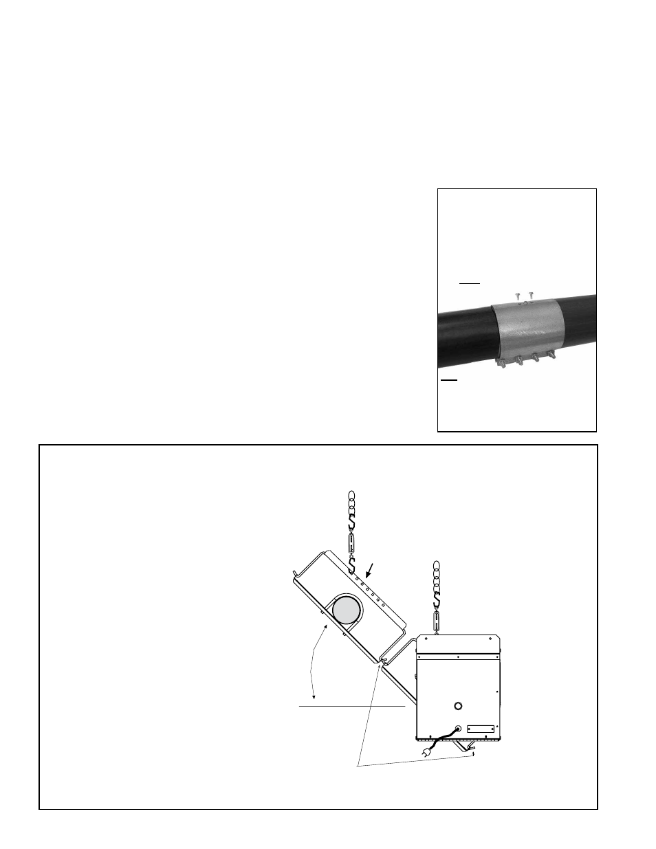
3. Connect the "U" Tube - Before the
"U" tube is connected, determine the
angle of the final installation (
See FIG-
URE 3). The "U" tube may be installed
so that the exhaust side of the system
is level with or rotated 15°, 30°, or 45°
above the burner/control box side.
Use the compression coupling in the
kit to attach the "U" tube following the
same procedure as the straight tubes,
but when inserting the "U" tube into
the coupling, the unattached side of
the "U" tube may be rotated so that
the exhaust side will be up to 15°, 30°,
or 45° higher than the control/burner
box side. When the "U" tube is at the
desired angle, tighten the coupling and
insert the two self-drilling screws to
hold it in place.
End View of a Model VR with an
Optional U Tube at a 45° Angle
0°, 15°,
30°, or 45°
Before operating
the unit, level the
tubes and close all
S hooks.
Hanger bar is designed with holes gauged
for 0°, 15°, 30°, or 45° suspension.
Rotate the U tube so that the exhaust end
is higher than the burner/control box side.
The end of retainer wire with the sharper 45°
bend must be on the lower side when reflectors
are angled (applies to all retainer wires).
Exhaust End
of U T
ube
Burner Box
FIGURE 3 - End View with "U"
System at a 45° Angle
•
Rotate the "U" tube in the coupling
to angle the tubes after the "U" tube.
(Exhaust end must be the higher
side.) Suspend from the appropriate
hole in the hanger bar.
•
On the tubes between the burner/
control box and the "U" tube, rotate
the reflector by loosening the nuts on
the "U" bolt (the same as a straight
system) and moving the suspension to
the appropriate hole in the hanger bar.
FIGURE 2 - After
determining the angle (see
FIGURE 3), use a coupling
to connect the "U" Tube to
the straight tube
Installation
Instructions
Reference Heater
Installation Manual,
Form I-VR
Installation should be done by a qualified agency in accordance with these instruc-
tions and in compliance with all codes and requirements of authorities having juris-
diction.
1. Install the burner/control box, combustion chamber tube, and any heat
exchanger tubes before the "U" tube. Carefully read and follow the instructions
in the heater installation manual.
2. Turbulator Strip Sections - If the "U" tube is adjacent to the exhaust heat
exchanger tube and the heater is 40 to 70 feet in length, install two sections
of the turbulator strip in the straight heat exchanger tube before attaching the
"U" tube. Follow the instructions in the heater installation manual for inserting
turbulator strips.
1st, Slide both the "U" tube
and the straight tube into
the coupling and tighten
the bolts
Illustration NOTE: For clarity, not all
tube hangers and chains are shown.
Burner/control box chains are not
shown.
Installation NOTES:
Each straight tube section must have
one or two suspension points.
“U” tube does not require a suspension
point.
Comply with all requirements in the
heater installation manual.
NOTE: Before installation,
wipe any excess corrosion
inhibitor from the heat
exchanger tubes. Failure
to do so could result in
excessive smoke from the
surface of the tubes on
initial startup.
2nd, Insert Self Drilling
Screws