Warn ing – Reznor R6GN Option - Installation - Power Exhaust User Manual
Page 2
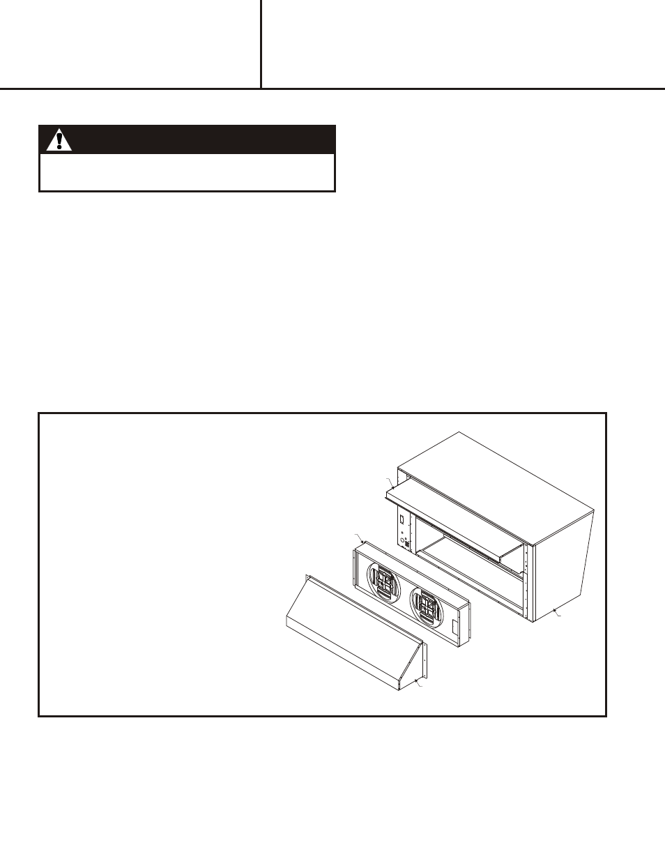
Down Flow Application
3a. Install the power exhaust where relief
hood was mounted using same holes and
screws from step 2.
POWER EXHAUST
UNIT
FRESH AIR HOOD
BAROMETRIC RELIEF HOOD
Fig ure 3
IN STAL LA TION
IN STRUC TION
INSTALLATION INSTRUCTIONS FOR
555622 / 555623
POWER EXHAUST USED WITH GR4GM-150/180 (R-22)
and R6GN-150/180 (R410A) UNITS
For GR4GM-150/180 (R-22) Models - Locate plug on the side of the economizer under economizer controls, insert
bushing, and route power exhaust control and supply wiring through economizer side panel. Connect to unit per
accessory wiring diagram. Power exhaust low voltage control wiring connects to EF and EF1 on the economizer W7212
logic module. Refer to the installation instructions provided with the economizer for proper set up and operation.
IMPORTANT: See unit rating label before operating this accessory to ensure correct field supply wire size has
been installed for proper operation.
For R6GN-150/180 (R410A) Models - Application of this accessory on R6GN-150/180 models requires a separate
branch circuit for proper operation.
Locate plug on the side of the economizer under economizer controls, insert bushing,
and route power exhaust control wiring through economizer side panel and connect to unit per accessory wiring diagram.
Power exhaust low voltage control wiring connects to EF and EF1 on the economizer W7212 logic module. Refer to the
installation instructions provided with the economizer for proper set up and operation. Removal of the 6 pin/4 wire harness
assembly from the LINE side of the power exhaust contactor is required prior to field wire attachment. See Table 1 or the
accessory rating label for proper branch circuit electrical requirements. (Field Supplied)
4.
Elec tri cal Con nec tions
Warn ing:
All electrical wiring must comply with the latest edition
of the National Electrical Code (NEC) - NFPA 70.