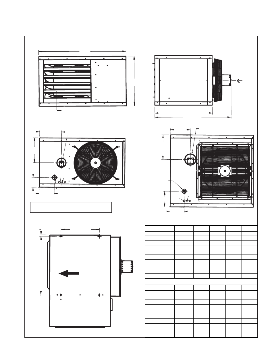
Dimensions, Model ft dimensions (inches and mm), Afront view all sizes – Reznor FT Unit Installation Manual User Manual
Page 6
Form RZ-NA-I-FT, Mfg No. 173473 Rev 8, Page 5
10. Dimensions
Model FT Dimensions (inches and mm)
A
Front View
All Sizes
Adjustable Louvers
B
5 dia Flue Outlet, Sizes 150-250
6 dia Flue Outlet, Size 300
Gas Connection
Sizes 150-200, 1/2 NPT
Sizes 250-300, 3/4 NPT
E
F
G
H
L
K
Rear View
Sizes
150-300
C
Removable Access Panel
Right Side View
All Sizes
Standard control side is
the right side; units may
be converted to left side
controls in the field (See
Paragraph 8.)
of Motor
D
4 dia Flue Outlet
Rear View
Sizes
30 - 125
E
1/2 NPT Gas Connection
F
G
H
K L
(4) 3/8-16 Cage Nuts for
4-point unit suspension
NOTE: Sizes 30, 45, 60, and 75
may be suspended with two-
point suspension. See Figure 3B.
M
Top View
All Sizes
16 (406)
J
Airflow
NOTE: Composite drawings are not proportional for all sizes.
Field Wiring
K
= 115V/60Hz/1Ph
Connections
L
= Thermostat Wires (24V)
Figure 4
Dimensions (inches)
Size
30
45
60,75
100,125 150,200 250,300
A
28-5/8
28-5/8
28-5/8
38
38
50-1/8
B
12-1/8
12-1/8
18-1/8
22-1/16
33-1/16
33-1/16
C
21-1/4
21-1/4
23-1/4
25-5/16
25-5/16
25-5/16
D
25-9/16
26-3/16
31-3/8
33-9/16
34
35-3/8
E
6-9/16
6-9/16
6-9/16
9-3/4
6-3/16
8-3/16
F
5-13/16
5-13/16
8-3/4
11-1/8
11-3/8
11-3/8
G
4
4
4-1/4
4-3/8
7-1/8
7-1/8
H
3-1/16
3-1/16
3-1/16
6-11/16
6-1/2
4-15/16
J
17-15/16
17-15/16 17-15/16 24-1/4
24-1/4
29-3/8
M
9/16
9/16
9/16
9/16
9/16
8-1/2
Dimensions (mm)
Size
30
45
60,75
100,125 150,200 250,300
A
727
727
727
965
965
1273
B
308
308
460
560
840
840
C
540
540
591
643
643
643
D
649
665
797
852
864
899
E
167
167
167
248
233
208
F
148
148
222
283
289
289
G
102
102
108
111
181
181
H
78
78
78
170
165
125
J
456
456
456
616
616
746
M
14
14
14
14
14
216