Reznor P6SP Option - Installation - Low Ambient - Light Commercial User Manual
Page 3
3
23. Install outdoor bracket cover plate over the control and
secure with the blunt point screw provided on the right
hand side of the cover plate.
24. Wipe off any excess dirt, moisture and/or oil from the
cover plate with a clean rag and install the supplied
warning sticker on front surface so that it is visible (see
Figure 1.)
25. Replace all unit panels.
26. Reconnect power to unit and set thermostat to desired
setting.
Note: If the pressure control is modulating the OD fan(s)
operation and the compressors discharge pressure is
fl uctuating, the unit charging charts provided in the installation
instructions can not be used to verify operation of the unit.
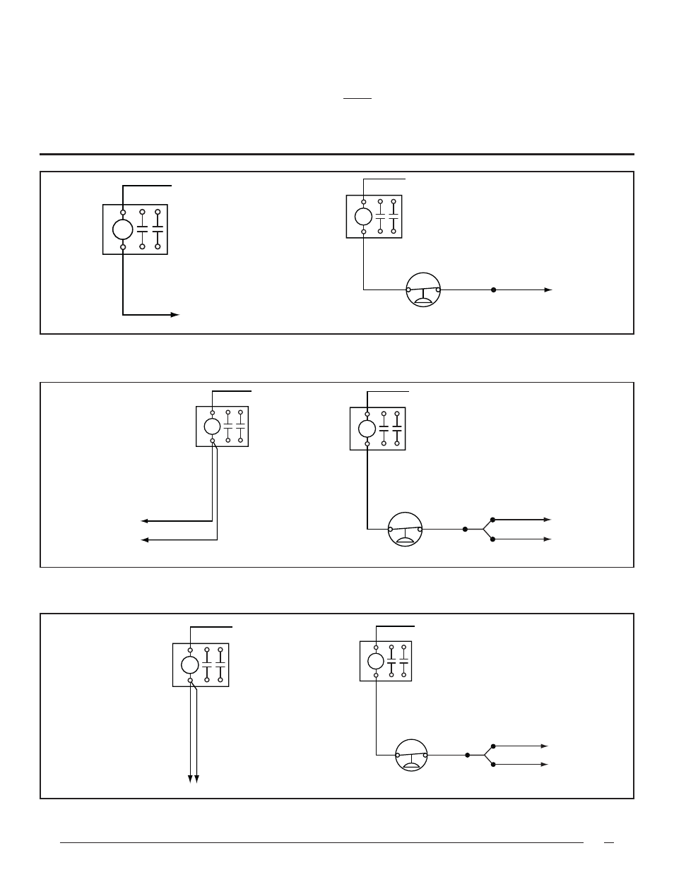
OUTDOOR
FAN
RELAY
TO N.O. ON AUX SWITCH
COMP 1 CONTACTOR
LOW AMBIENT
PRESSURE SWITCH
VIOLET
ORANGE
ORANGE
1
4
24V (COM)
L2
L1
T2
T1
OUTDOOR
FAN
RELAY
TO N.O. ON AUX SWITCH
COMP 1 CONTACTOR
ORANGE
24V (COM)
L2
L1
T2
T1
Figure 4. 6T WD
Before
Figure 6. 7-1/2 & 10T WD
Before
Figure 8. 12-1/2 & 15T WD
Before
Figure 5. 6T WD
After
Figure 7. 7-1/2 & 10T WD
After
Figure 9. 12-1/2 & 15T WD
After
OUTDOOR
FAN
RELAY
7-1/2 TON - ORANGE
10 TON - RED
7-1/2 TON - ORANGE
10 TON - RED
TO N.O. ON AUX SWITCH
COMP 1 CONTACTOR
TO N.O. ON AUX SWITCH
COMP 2 CONTACTOR
24V (COM)
L2
L1
T2
T1
OUTDOOR
FAN
RELAY
7-1/2 TON - ORANGE
10 TON - RED
VIOLET
1
4
7-1/2 TON - ORANGE
ORANGE
JUMPER
ORANGE
10 TON - RED
TO N.O. ON AUX SWITCH
COMP 1 CONTACTOR
TO N.O. ON AUX SWITCH
COMP 2 CONTACTOR
24V (COM)
L2
L1
T2
T1
OUTDOOR
FAN
RELAY
VIOLET
1
4
YELLOW
ORANGE
PIN 2
PIN 3
JUMPER
ORANGE
24V (COM)
L2
L1
T2
T1
PIN 3,
ECON HARNESS PLUG
PIN 2,
ECON HARNESS PLUG
OUTDOOR
FAN
RELAY
YELLOW
PIN 2,
ECON HARNESS PLUG
YELLOW
PIN 3,
ECON HARNESS PLUG
24V (COM)
L2
L1
T2
T1