Reznor R6GF Option - Installation - Low Ambient Control - Light Commercial User Manual
Page 2
O’Fallon, MO
708175C (Replaces 708175B)
Specifi cations and illustrations subject to change
without notice and without incurring obligations.
Printed in U.S.A. (07/06)
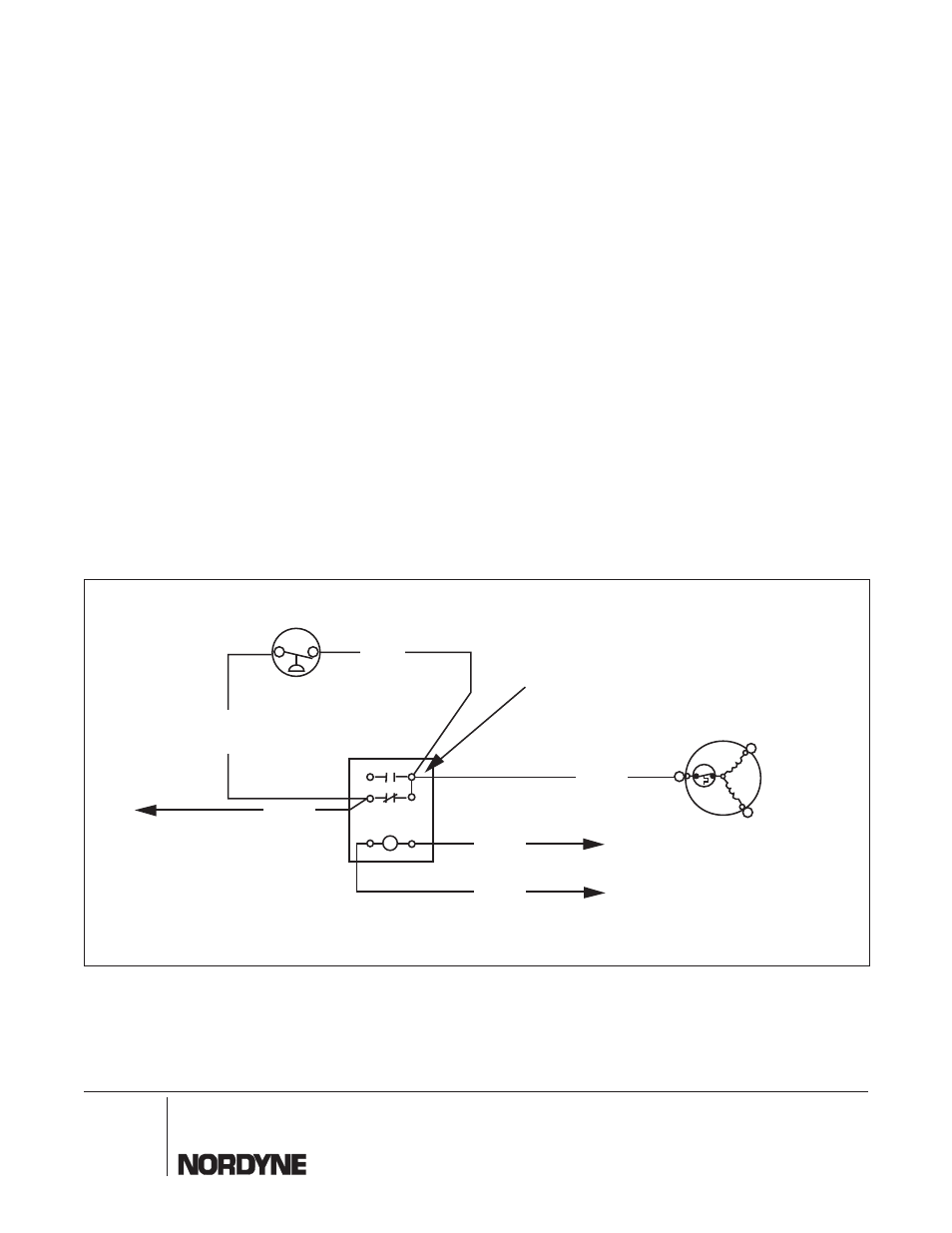
b) Connect the two black wires to terminals #1 and
#3 on the relay and route the wires through the low
voltage divider. Connect one black wire to “O” on
the defrost board. Connect the other black wire
to 24V common ( “C” on the defrost board).
c) Connect the “Y” adapter terminal, provided with
the kit, to terminal #4 of relay.
d) Remove the black outdoor fan motor wire from
“DF2” on the defrost board and connect it to the
adapter on terminal #4 of relay.
e) Connect the piggyback end of the white wire to
terminal #5 of relay and connect the other end to
“DF2” on the defrost board.
f) Connect one wire lead from the pressure switch
to terminal #5 of relay and the other to terminal
#4 of relay.
8. Tie all wires back as needed.
9. Replace the service panels removed in Steps #2
through #5.
10. Restore power to the unit.
6. Remove the cap from the service valve. Mount the
service adapter tee, provided with kit, onto the service
valve and tighten. Mount the pressure switch onto
the port of service adapter that does not have valve
core and tighten. Replace the cap, removed from the
service valve, onto service port of adapter tee that
includes a valve core.
7. Route the two wire leads from the switch through the
wire grommet at the top of the panel separating the
compressor from the control box.
A. For Air Conditioners
a) Remove the fan motor common lead from “T2” on
the contactor (black wire).
b) Using wire splice provided connect one lead from
the pressure switch to the fan motor lead.
c) Connect the other pressure switch lead to “T2” on
the contactor. (See Figure 1)
B. For Heat Pumps
a) Mount the relay provided in the control box, near
the low voltage compartment.
Figure 2. Heat Pump Low Ambient Control Kit Wiring Diagram
Low Ambient
Control
BLACK
C
S
R
Outdoor Fan
Motor
4
2
5
1
6
WHITE
To "DF2" on
Defrost Board
(Y Adapter Terminal)
BLACK
BLACK
To "C" on Defrost Board
To "O" on Defrost Board
3
BLUE
BLUE
¢7081759¤
708175C
- R6GD Option - Installation - Low Ambient Control - Light Commercial Q6SD Option - Installation - Low Ambient Control - Light Commercial P6SD Option - Installation - Low Ambient Control - Light Commercial DF6SF Option - Installation - Low Ambient Control - Light Commercial R8GD Option - Installation - Low Ambient Control - Light Commercial