Installation drawings, Air flow requirements – Reznor B5SM Option - Installation - Heater Kit User Manual
Page 2
21. The heater must be wired so
that it cannot operate unless air is
flowing over it. This can be accom-
plished by using a built-in airflow
switch, a built-in fan relay or any of
several other methods. See the
accompanying wiring diagram for
the method used with this heater
and provide appropriate interlock
wiring as illustrated.
22. National Electrical Code and
Underwriters Laboratories require
the heater manufacturer to supply
1) over-current protection where
heater total current exceeds 48
amperes and 2) any contactors
required for proper functioning of
temperature limiting controls.
Where these devices are not in-
cluded in the heater terminal box
of a UL listed heater, they are sup-
plied in a remote UL listed panel
board shown on the wiring dia-
gram.
23. If not supplied as part of this
heater, install a line disconnect
switch or main circuit breaker in
accordance with the National Elec-
trical Code. Depending upon the
heater’s location and accessibility,
a built-in disconnect switch may
meet this requirement.
24. All electrical connections in
the heater, including both field and
factory made connections, should
be checked for tightness before
operating the heater. In addition,
after a short period of operation, all
connections should again be
checked for tightness.
25. If heater is wired to a heating-
cooling thermostat, use a thermo-
stat with isolating circuits to prevent
possible interconnection of Class
2 outputs.
26a. If the area inside of the sheet
metal directly surrounding the heat-
ing element section is more than
1” smaller in length and/or width
than the duct in which the duct
heater is installed, the KW per
square foot of duct area should be
calculated as the heater nameplate
KW divided by the area inside the
sheet metal enclosure directly
around the heating elements.
26b. If the heating elements are
divided into several sections with
uncoiled resistance wire between
two or more coiled sections, maxi-
mum KW per sq. ft. should be cal-
culated as follows:
Heater nameplate KW
Number of heated sections x
area of one heated section
OPERATION & MAINTENANCE
NOTICE: ALL SOURCES OF SUPPLY MUST BE DISCONNECTED
BEFORE WORKING ON THIS EQUIPMENT
425 Hanley Industrial Court * St. Louis, Missouri 63144
(314) 644-4300 * FAX (314) 644-5332
To operate this heater make sure all associated control
equipment is on, energize main supply disconnect and
set controlling thermostat above ambient temperature.
This heater is equipped with automatic and manual reset
temperature limiting controls. If it fails to operate, make
sure manual resets are operative by pushing reset
buttons.
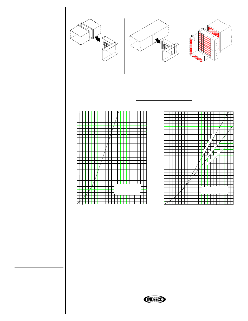
INSTALLATION DRAWINGS
Fig. 1 – Installation drawing of
flanged heater.
Fig. 2 – Installation drawing of slip-in
heater.
Fig. 3 – Installation drawing of two
stacked sections in a duct.
AIR FLOW REQUIREMENTS
Calculate KW per square foot of duct area as:
heater namplate KW
duct area (Sq.Ft.)
Fig. 5 –
Fig. 4 –
100
2
200 300 400 500 600 700 800 900 1000 1100 1200
4
6
8
10
12
14
16
0
0
100
2
200 300 400 500 600 700 800 900 1000 1100 1200
4
6
8
10
12
14
16
18
22
24
26
28
30
32
20
0
0
KW PER SQ. FT. DUCT AREA
MINIMUM AIR VELOCITY REQUIRED
(FEET PER MINUTE)
KW PER SQ. FT. DUCT AREA
MINIMUM AIR VELOCITY REQUIRED
(FEET PER MINUTE)
(see #26)
The only routine maintenance required is to check all
electrical connections, including field and factory made
connections, for tightness at least once each year or
operating season. In addition, of course, any filters in the
airstream must be kept clean so that adequate airflow is
maintained.
FINNED
TUBULAR
CONSTRUCTION
91 - 100° Inlet Air
81 - 90° Inlet
Air
Below
80° Inlet A
ir
OPEN COIL
CONSTRUCTION
092d-1108