Reznor R6GN Option - Installation - Current Sensing Lockout User Manual
Page 2
X-
3-
-2
-1
L1
L2
L3
Black
Red
Blac
k/White
F
actor
y Blac
k/Red
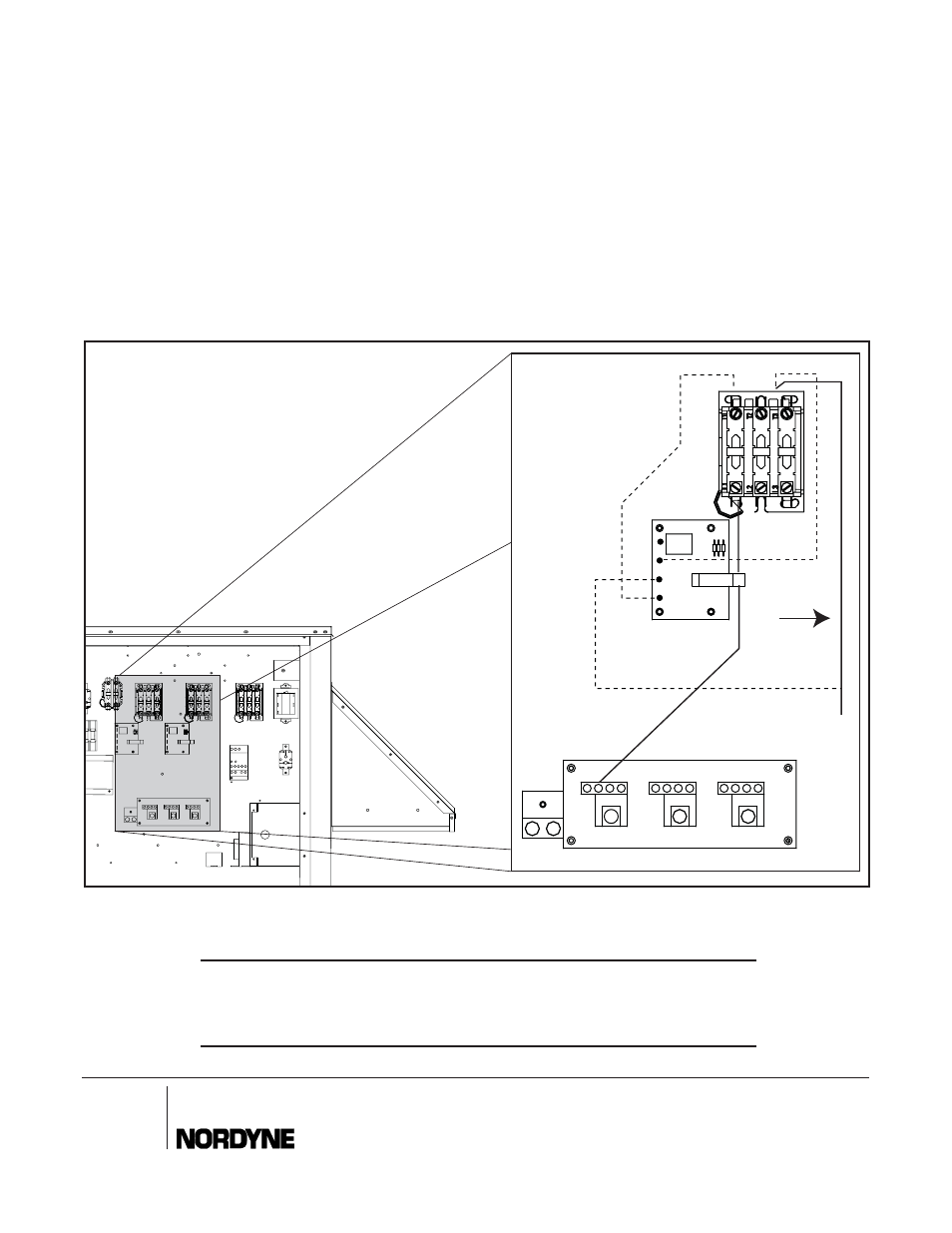
See Step 5
Factory
Black/Red
SEE FIGURE 2 FOR REMAINING STEPS
5. Remove the Black/Red wire (Cooling Y1) from the
24V coil connection located at the top of Stage 1
compressor contactor and re-attach to Terminal # 2
on the Stage 1 sensing board.
6. Attach Red wire from Stage 1 sensing board Ter-
minal # 3 back to compressor 24V contactor coil
where Black/Red (Cooling Y1) wire was removed.
7. Attach remaining Black wire with piggyback terminal
from sensing board Terminal # 1 to the other side of
the 24V compressor contactor coil. (24V Com)
O'Fallon, MO
7084850
Specifi cations and illustrations subject to change
without notice and without incurring obligations.
Printed in U.S.A. (08/05)
¢708485J¤
7084850
INSTALLER: PLEASE LEAVE THESE INSTALLATION
INSTRUCTIONS WITH THE OWNER
Figure 2.
8. Repeat Steps 5, 6, and 7 for Stage 2 compressor
circuit. (Cooling Y2)
9. Remove the “L1” line voltage wire to Stage 1 com-
pressor (Black/White) from the unit terminal board,
carefully pass wire through Stage1 lockout board
sensing loop, and reconnect back to the unit termi-
nal board.
10. Repeat this for Stage 2 “L1” line voltage wire to
Stage 2 compressor.
11. Restore all Electrical power back to unit and check
for proper unit operation.