Reznor B Option - Installation - Relay & Thermostats Installation User Manual
Page 2
Form RZ-NA-I-F/B-R, Page 2
6. Replace the heater side panel.
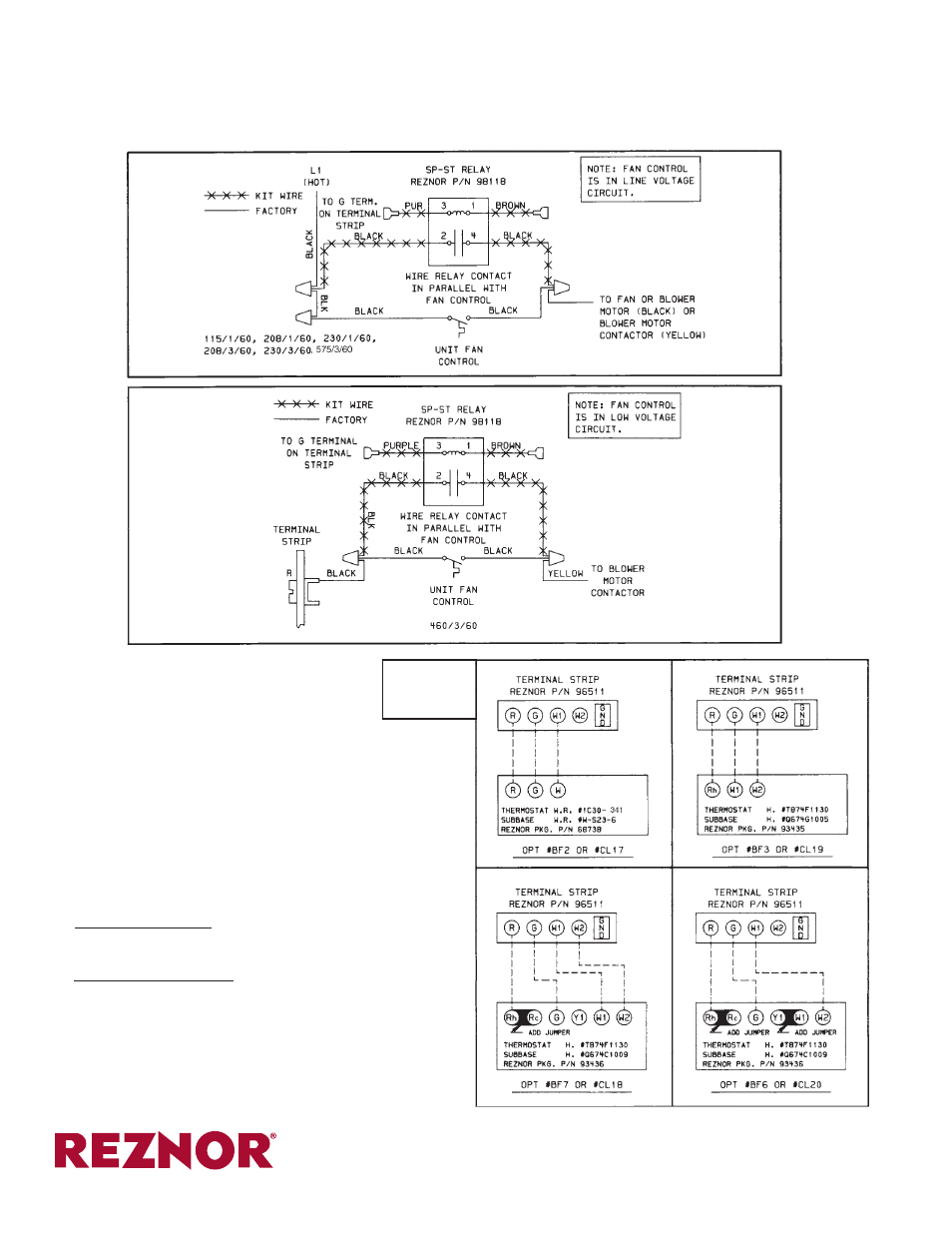
7. The diagrams in Figure 4 illustrate wiring connections when this
relay is used in conjunction with Reznor optional thermostats.
Follow these connection diagrams whether using a thermostat from
Reznor or a field-supplied equivalent thermostat. (Relay Option
CL21 does not include a thermostat.)
8. If the heater is installed, turn on the electric power and the gas.
Relight following the instructions on the heater. Check the opera-
tion of the controls.
If the heater is not installed, be sure to support the bottom with
plywood or other appropriate material when the heater is sus-
pended.
Follow the installation instructions provided with the heater. Check
for proper operation of the controls.
5. Check the supply voltage of your
heater and choose the appropriate
wiring diagram.
Route the purple wire and the brown wire through the cable holders. (If the heater has a metal horizontal partition in place of a cable holder, route
the wires through the vacant hole and insert the open/closed bushing in the hole.)
• Figure 2 for 115, 208, 230, or 575 volt.
• Figure 3 for 460 volt.
INSTALLATION NOTE: On heaters equipped with two-stage con-
trols, the brown wire must be connected to the ground terminal on the
terminal strip or on the ignition controller.
800-695-1901
www.RezSpec.com
©2014 Reznor, LLC. All rights reserved.
Printed in U.S.A.
MANUFACTURER OF GAS, OIL, ELECTRIC HEATING AND VENTILATING SYSTEMS
Trademark Note: Reznor
®
is registered in the United States and other countries.
0514 OG POD Form RZ-NA-I-F/B-R (Version 0.1)
TO THE GROUND TERMINAL ON THE
TERMINAL STRIP OR TO THE TERMINAL
STRIP ON THE IGNITION CONTROLLER
TO THE GROUND TERMINAL ON THE TERMINAL
STRIP OR TO THE TERMINAL STRIP ON THE
IGNITION CONTROLLER
Figure 4 -
Thermostat
Wiring
Figure 2 -
Wiring for
115, 208, 230,
or 575 volt
Figure 3 -
Wiring for
460 volt