Installation instructions (co ()nt’d) – Reznor B Option - Low Ambient Control Relay Installation User Manual
Page 2
Form 434/436-LA, Page 2
(800) 695-1901
www.RezSpec.com
©2014 Reznor, LLC. All rights reserved.
Printed in the U.S.A.
MANUFACTURER OF GAS, OIL, ELECTRIC HEATING AND VENTILATING SYSTEMS
Trademark Note:
Reznor
®
is registered in the United States and other countries.
0514 POD OG Form I-F/B-LA (Version 0.1)
Installation Instructions (co ()nt’d)
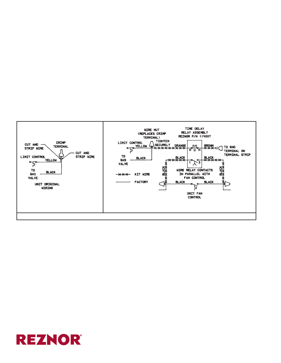
4. Electrical Wiring –
Route the brown and orange wire down
through either the vacant hole (See Figure 1) in the horizon-
tal partition or the cable holder. If the heater has a metal par-
tition, insert the open/closed bushing included in the kit.
In order to connect the orange wire to the factory wires, it
will be necessary to remove a factory-installed crimp termi-
nal. See the original wiring portion (left side) of the wiring
diagram in Figure 2.
Locate and cut off the crimp terminal. Strip the yellow and
black factory-installed wires. Using the wire nut in the kit,
connect the new orange wire with the yellow and black wires.
Connect the brown wire to the ground terminal on the heater
terminal strip.
Connect the new black wires shown on the relay portion (right
side) of the wiring diagram in Figure 2.
5.
Replace heater side panel.
6.
If the heater is installed, turn on the electric power and the
gas. Re-light the heater following the instructions on the light-
ing instruction plate. Check the operation of the fan control.
CHECK FOR PROPER OPERATION OF ALL SAFETY
FEATURES.
If the heater is not installed, be sure to support the bottom
with plywood or other appropriate material. Follow the in-
stallation instructions provided with the heater and check for
proper operation of the controls.
:
Figure 2 - Wiring Diagram
Original Factory Wiring Showing
Location of Crimp Terminal
Electrical Connections for Low Ambient Relay Option