Reznor OB Option - Installation - Draft Booster Relay User Manual
Option dh1 draft booster relay package, Installation instructions, Sequence of operation
Form RZ-NA-I-OIL-DBR, Mfg #110781, Page 1
APPLIES TO:
Models OH andOB
Models RA and RAD 110/140/235/350/500
Option DH1 Draft Booster
Relay Package
INSTALLATION FORM RZ-NA-I-OIL-DBR
Obsoletes Form RZ-NA 417/461&4-DBR
WARNING: Incorrect installation of the draft
booster relay and/or field supplied draft booster
could cause property damage, personal injury, and/
or death.
Description/Application
Option DH1, Draft Booster Relay Package, includes the required relay,
hardware, and wires to provide proper operation of a field-supplied
draft booster on a Reznor
®
oil-fired unit heater.
The option package (P/N 110780) includes:
Qty
P/N
Description
1
103318
RBM Relay, Essex #134-50203-301
2
38529
Sheet metal screws, #8 x 1/2" long
1
110774
White Wire Assembly consisting of 6" long,
18-gauge, 105°C white wire with one terminal
1
110775
Orange Wire Assembly consisting of 5" long,
18-gauge, 105°C orange wire with one terminal
1
110777
Black Wire Assembly consisting of 7" long,
14-gauge, 105°C black wire with one terminal
1
110779
Red Wire Assembly consisting of 4" long,
14-gauge, 105°C red wire with one terminal
1
111066
Yellow Wire Assembly consisting of 5" long, 14-
gauge, 105°C yellow wire with one terminal
1
16354
Wire Nut #73B
Installation Instructions
These instructions are designed to assist a qualified electrician in in-
stalling this draft booster relay. All electrical wiring and connections,
including electrical grounding, MUST be in accordance with the Na-
tional Electric Code ANSI/NFPA No. 70 (latest edition) or, in Canada,
with the Canadian Electrical Code, Part 1-C.S.A. Standard C22.1 In
addition, the installation must comply with local ordinances.
1. Assemble the relay and wires. The wire connections on the relay are
numbered. Push the terminals onto the proper connections.
Terminal No. 1- 6", 18 gauge white wire.
Terminal No. 2- 7", 14 gauge black wire.
Terminal No. 3- 5", 18 gauge orange wire.
Terminal No. 4- 5", 14 gauge yellow wire.
Terminal No. 5- 4", 14 gauge red wire.
2. Turn off the electrical power to the unit by putting the disconnect
switch in the “off” position.
3. Open the main electrical box on the end of the heater. Above the
terminal blocks, there is provision made to add a row of relays in the
junction box. The draft booster relay is designed for the extreme left
position. Using the two screws provided, fasten the relay in this
position.
4. Above the draft booster relay, remove one of the hole plugs in the
top of the electrical box. Use this for entry of the draft booster
wiring.
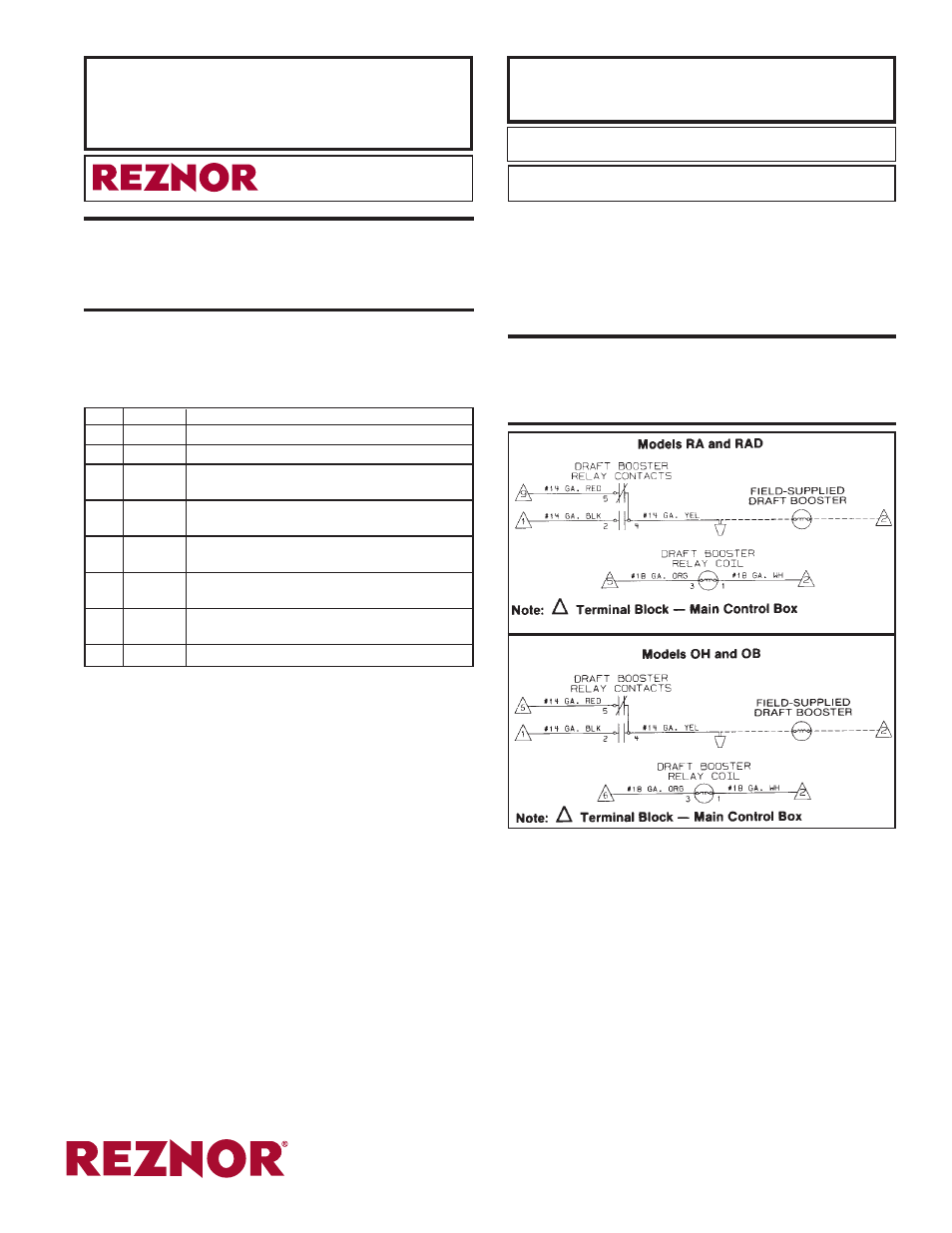
5. Following the appropriate wiring diagram below and the wiring
diagram on the heater, make the proper wire connections. Use the
wire nut to attach the 14-gauge yellow wire to the draft booster field
wiring. The field-supplied draft booster must include proof of flow
contacts (exhaust flow switch). This switch must be capable of
handling a 7.5 amp inductive load. Wire these contacts according to
the diagram on the heater.
WARNING: Orange jumper wire must be
removed. Models RA/RAD, orange wire is between
Terminals 5 and 6; Models OH/OB, orange wire
is between Terminals 6 and 7.
800-695-1901 www.RezSpec.com
©2014 Reznor, LLC. All rights reserved.
Printed in the U.S.A.
Trademark Note:
Reznor
®
is registered in the United States and other countries.
0514 POD OG Form I-OIL-DBR (Version 0.1)
6. Close the electrical box. Turn on the power by putting the discon-
nect switch in the “on” position.
7. Check for proper operation of the draft booster and heater.
Sequence of Operation:
Start-Up
1) Thermostat calls for heat, energizing ignition controller.
2) Ignition controller activates draft booster relay which energizes draft
booster motor.
3) Exhaust flow switch closes, activating the burner motor and fuel
valve.
4) Heater fires and operates until thermostat is satisfied.
Shutdown
1) Thermostat shuts off power to ignition controller.
2) Draft booster motor and fan/ blower continue to operate until fan
control is cooled (approximately 2-1/2 minutes).
®