Reznor BE Option - Installation - Summer/Winter Blower Switch Instructions User Manual
Option ch1 manual summer/winter blower switch, Option description, Installation instructions
Form I-B-SW, Mfg No. 101678, Page 1
APPLIES TO:
Models B and BE
OPTION CH1 MANUAL
SUMMER/WINTER
BLOWER SWITCH
INSTALLATION FORM RZ/NA I-B-SW
Obsoletes Form RGM 434/436-SWB (Version .1)
®
Option Description
The optional summer/winter switch is designed to provide manual
control of blower operation.
The option package includes:
OPTION CH1
B and BE
Manual Summer/Winter
25-400
Blower Switch
Qty
P/N
Option Package P/N
101679
Summer/Winter Switch, McGill #TS-71-6A
1
3745
Relay, Essex #134-20102-101
1
98118
Plastic Dart Fasteners
2
101798
Black Wire Assembly, 14 gauge x 8" long
2
101677
Purple Wire Assembly, 18 gauge x 18" long
1
101554
Purple Wire Assembly, 18 gauge x 8" long
1
101553
Brown Wire Assembly, 18 gauge x 18" long
1
101676
Wire Nut 73B, Ideal #3-0253
2
16354
Wire Nut 74B, Ideal #3-0274
1
16355
Plastic Strap Ty-Rap #Ty B24M
1
20913
Open/Closed Bushing, Heyco #OCB-500
1
98117
(required for units with lower horizontal partition;
not required on units with cable holders - See
Figure 1)
Installation Instructions
Installation should be done by a qualified agency in accor-
dance with these instructions and in compliance with all codes
and requirements of authorities having jurisdiction.
1. If the heater is installed, turn off the gas and turn off the elec-
trical power.
2. Remove the outer side panel on the left side of the heater (left
when facing the back of the heater), exposing the inner side
panel and wiring.
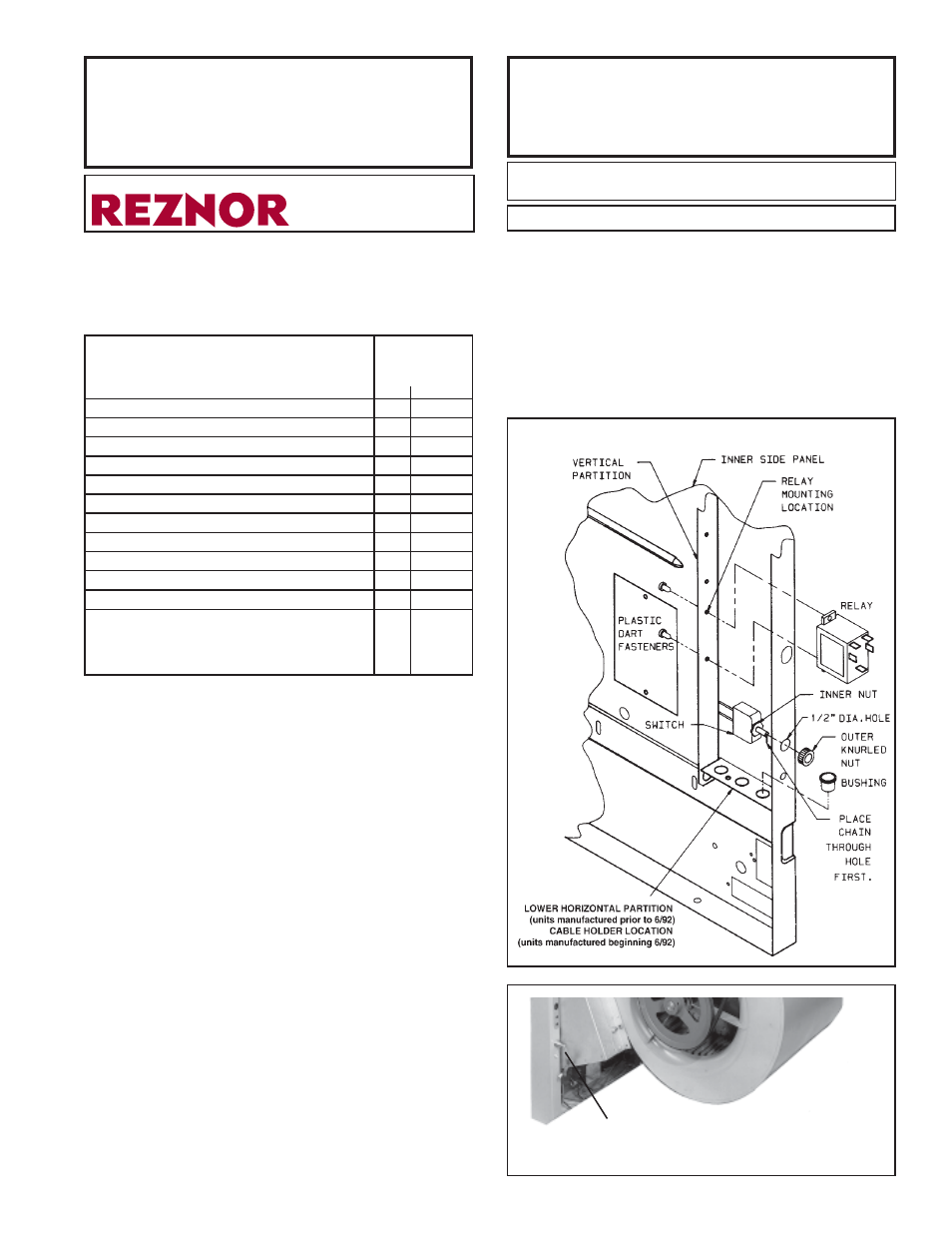
3. On the rear edge of the inner side panel, locate a 1/2” diam-
eter hole ( See Figure 1). Insert the chain and the front of the
switch through the hole. Arrange the knurled nut as shown in
Figure 1 and tighten firmly by hand.
4. On the vertical partition of the inner side panel, locate the
pre-punched holes for mounting the relay. See Figure 1. Hold
the relay in place and attach it with two plastic fasteners.
NOTE:
On units equipped for use with 460/3/60 power supply,
the relay is not used.
5. Wire the summer/winter switch and relay as shown on the
specific wiring diagram included with your heater or refer to
the general diagrams on the reverse side of this sheet. Check
the supply voltage of your heater and choose the appropriate
general diagram.
6. Replace the heater side panel.
Figure 1 - Installation of Summer/Winter Switch for
Blower Operation
Figure 2 - Summer/Winter Switch Installed
WARNING: Improper installation, adjustment,
alteration, service or maintenance can cause property
damage, injury or death. Read the installation, operation,
and maintenance instructions thoroughly before installing
or servicing this equipment.
7. Install the pull cord on the summer/winter switch.
8. If the heater is installed, turn on the electric power and the
gas and re-light, following the instructions on the heater. Check
the operation of the summer/winter switch. CHECK FOR
PROPER OPERATION OF ALL SAFETY FEATURES.
If the heater is not installed, be sure to support the bottom
with plywood or other appropriate material. Follow the in-
stallation instructions provided with the heater and check for
proper operation of the summer/winter switch.
Manual Summer/Winter Blower Switch