Installation instructions – Reznor BE 25-100 Option - Installation - Stepdown Transformer Installation (Options CF and CG) User Manual
Page 2
Form I-F&B-X, PN 102265R5, Page 2
Installation should be done by a qualified agency in accordance with the instructions on this
sheet and in compliance with all codes and requirements of authorities having jurisdiction.
Installation
Instructions
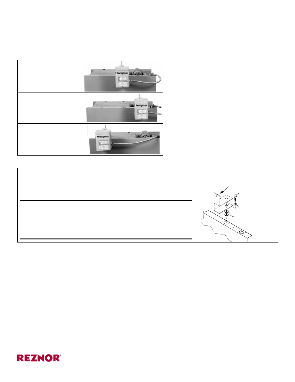
Transformer
Locking Screw
(1/2” lg Sheet-
metal Screw)
Bracket
Assembly
5/16 x 3/4” lg
Hex Head Cap
Screw
5/16 Lockwasher
(2) 5/16 Flat
Washers
1. Determine Correct Position for the Transformer Bracket
The bracket is always attached to the heater at a hanger bracket on the same side of the
heater as the field supply wiring connection. Depending on the type of heater, there are
three possible positions for installing the bracket. Read the following and determine the
correct location for your particular installation.
IMPORTANT: The bracket for the stepdown transformer MUST
be installed prior to suspending the heater. DO NOT fasten the
transformer to the bracket before the heater is suspended.
When suspending the heater, remember that due to the trans-
former bracket, suspension is 2” closer at that point.
Instructions:
1) Place the two flat washers over the hanger bracket hole.
2) Place the transformer bracket and lockwasher in the positions shown.
3) Attach these parts to the heater with the 5/16 x 3/4” long hex head screw.
FIGURE 5 - Install Transformer Bracket
FIGURE 2 - Transformer
Location on a Heater
with 2-Pt Suspension
FIGURE 3 - Transformer
Location on a Heater
with 4-Pt Suspension (no
optional blower cabinet)
FIGURE 4 - Transformer
Location on a Heater with
4-Pt Suspension (with
optional blower cabinet)
• Model F and FE with Two-Point Suspension -
- Select center suspension point (Remove and
discard the side panel screw that is located next
to this hanger bracket). (See
FIGURE 2.)
• Model F and FE with Four Point Suspension and
Model B and BE without an Optional Blower/Filter
Cabinet -- Select suspension point closest to the
field supply wiring connection. (See
FIGURE 3.)
• Model B and BE with Optional Blower /Filter Cab-
inet -- Select suspension point closest to the front
of the heater. (See
FIGURE 4.)
2. Install Transformer Bracket
The bracket is designed to become a part of the sus-
pension of the heater and has a threaded rod hanger
hole identical to the one on the heater. The length of
heater suspension required at this point will be short-
ened by two inches.
Follow the instructions in
FIGURE 5.
3. Install and Wire the Stepdown Transformer (Be certain power is OFF.)
1) Feed the wires through the conduit and place an anti-short bushing on each end of the conduit.
2) Attach the straight connector to the knockout hole in the side of the transformer.
3) Feed the wires into the connector and attach it to the conduit.
4) Hang the transformer on the bracket that was attached to the heater before suspension. Insert the locking screw as
shown in
FIGURE 5.
5) Following the diagram and connection information on the transformer, make the wiring connections. Since the trans-
former has dual primary and secondary voltages, extra care should be taken in making these connections.
6) Attach the 90° connector to the threaded hole on the heater for the supply wiring connection. Feed the wires through
the connector and attach the connector to the conduit. Form a loop in the conduit between the transformer and the
heater to take up any excess length. (Conduit provided is the same length for all suspension point locations.) See
FIGURE 2, 3, or 4.
7) Remove the wire access panel and make the wiring connections according to the diagram on the heater. Replace
the panel.
4. Turn on the electric power and the gas and light the heater following the instructions on the lighting instruction
plate.
www.ReznorHVAC.com; (800) 695-1901
© 2014 Reznor, LLC. All rights reserved.
*Trademark Notes: Reznor
®
is registered in at least the United States.
All other trademarks are the property of their respective owners.
0514 Form I-F&B-X (Version A.1)