Installation instructions (cont’d), Ductwork, Model b or be model udbp or udbs – Reznor BE Option - Installation - Duct Flange Assembly (Options CD9) User Manual
Page 2
Form RZ-NA I-OPT-DF, P/N 101192 (Rev 2), page 2
Top Front
Panel
Duct Flange
Top
Duct
Flange
Bottom
Outer
Tab
Bottom Front Panel
(remove screws to
attach duct flange)
Duct Flange Side
Installation Instructions (cont’d)
FIGURE 3 - Installing Duct Flange on Model UDBP or UDBS
Attach Sections - In the discharge opening, position one L-shaped section on
the left side and across the top. Line up the vertical section with the holes in
cabinet; attach with sheetmetal screws. Using the clearance holes in the duct
flange as a guide, drill 1/8” holes across the top of the heater cabinet opening.
Attach with sheetmetal screws.
Position the second duct flange section so that the top corner is inside the already
installed section and the bottom corner on the outside. Attach up the side using
the holes in the cabinet. Using the clearance holes in the duct flange as a guide,
drill 1/8” holes across the bottom of the heater cabinet opening. Attach with
sheetmetal screws.
At the two corners where the sections meet, attach sections with a sheetmetal
screw; insert screws with points to inside of duct flange.
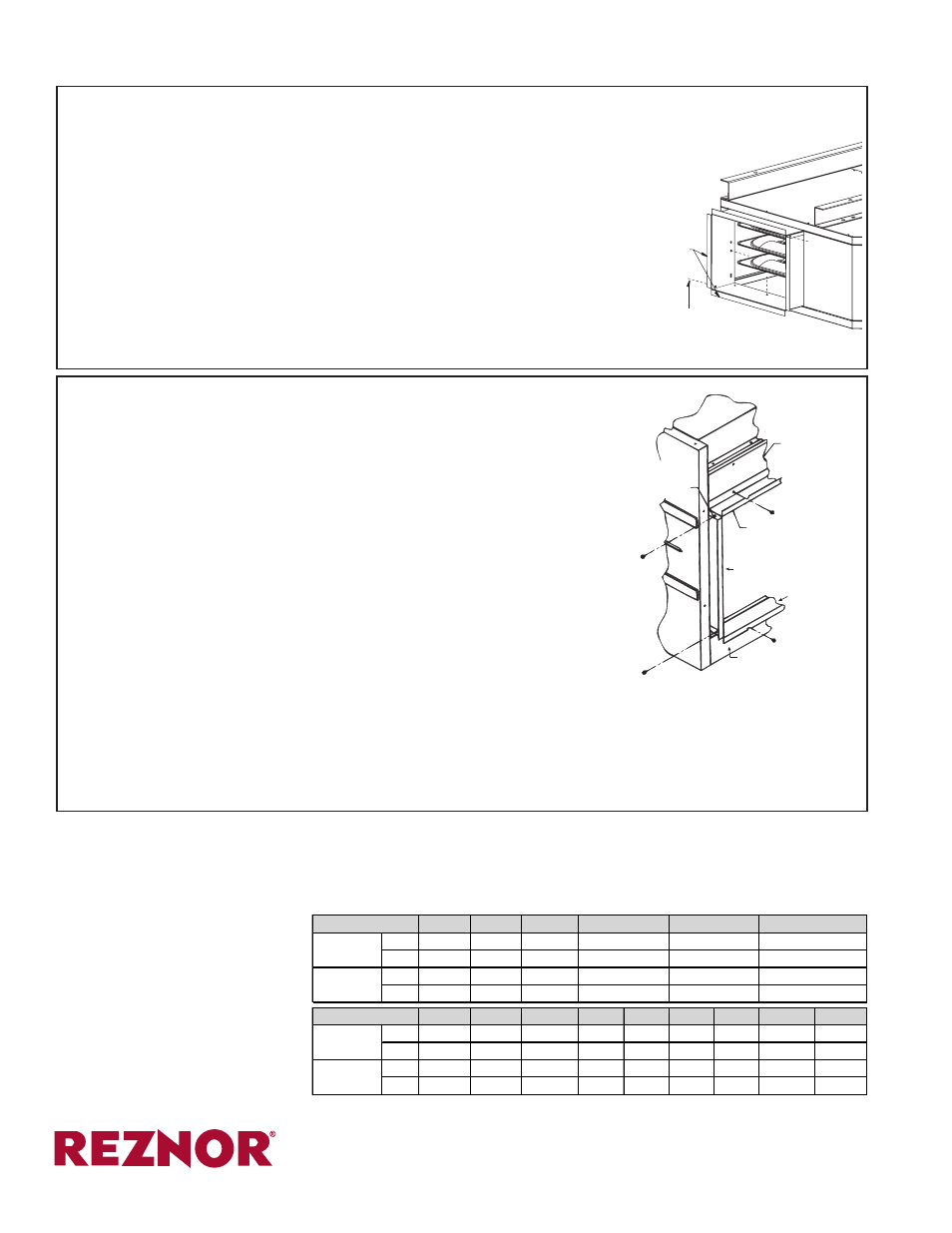
FIGURE 4 - Installing Duct Flange on Models B and BE
4. When the duct flange and ductwork is complete, turn on the electric power
and the gas. Follow the instructions on the lighting instruction plate to relight
the heater. Check for proper operation.
Ductwork
Ductwork should be fitted over
the vertical flange and fastened
to the top, bottom and sides with
sheetmetal screws. Seal joints
with duct tape to prevent air leaks.
Properly sized ductwork based on
CFM and static pressure is re-
quired for a good heating instal-
lation. All supply ducts should be
equipped with dampers so that air
delivery may be balanced.
Duct Connection Dimensions - including 3/4" (19mm) duct flange
30, 45
60, 75 100, 125
inches
15-5/16 15-5/16
15-5/16
mm
389
389
389
inches
11-1/2
14-1/2
22-1/2
mm
292
368
572
25, 50
75
100
125
130
165
200
250, 300
400
inches
12-1/4 14-1/4
16-1/4
22
16-1/4
19
22
27-1/2
35-3/4
mm
311
362
413
559
413
483
559
699
908
inches
17-3/8 17-3/8
17-3/8 17-3/8 23-7/8 25-3/8 25-3/8 25-3/8
25-3/8
mm
441
441
441
441
606
606
606
606
606
800
300, 350, 400
24-1/2
622
31-1/2
Height
150, 175, 200
24-1/2
622
17-1/2
445
Width
Height
B and BE
Width
225, 250
24-1/2
622
23-1/2
597
UDBP and UDBS
(800) 695-1901; www.ReznorOnLine.com
©2014 Reznor, LLC. All rights reserved.
Printed in the U.S.A.
MANUFACTURER OF HEATING, COOLING, AND VENTILATING SYSTEMS
Trademark Note: Reznor
®
and
T
CORE2
®
are registered in at least the United States.
0514 Form I-OPT-DF (Version 0.1)
(2) Duct
Flange
L-Shaped
Sections
Sheetmetal
Screws
Model B
or BE
Model UDBP
or UDBS
Attach Sides (Duct flange sides are interchangeable; there is no right or left piece.)
- Position a side piece in the heater opening with the duct flange toward the outside;
match two holes with the holes from the louver assembly that was removed in Step
2. Using the screws removed from louver assembly, attach the duct flange side at
the two holes. Repeat to attach the other side.
Additional screws are required on each side. On Sizes 25-125, two additional screws
are required; on Sizes 130-400, three additional screws are required per side. Drill
3/32" diameter holes in both inner side panels of the heater.
Use the 3/8" long screws to finish attaching the duct flange sides. (Since the duct
flange sides are interchangeable, there will be one hole at each end that is not used.)
Attach Duct Flange Top and Bottom (see illustration)
Top: 1) Position the duct flange top with the outer tabs down over the outside of
the side pieces.
2) Using the holes in the heater top front panel, attach the duct flange top.
3) Insert the corner screws in the top and the sides with the screw ends to the inside of the duct flange.
Bottom: 1) Remove and save the screws from the bottom front panel of the heater.
2) Position the duct flange bottom with the tabs over the sides.
3) Attach, re-inserting the screws removed from the front of the heater.
4) Insert the corner screws (with points to the inside), attaching the bottom and sides of the duct flange.