Installation instructions (cont'd), Install discharge panel (see figure 8), Attach label – Reznor BE Option - Installation - Polytube Adapter - Suspended Unit User Manual
Page 4: Install polytube (see figure 8), Installation checks
INSTALLATION INSTRUCTIONS (cont'd)
5. Install Discharge Panel (See Figure 8)
Slide the discharge panel over the front of the "box" formed by the sides, top, and
bottom adapter panels. Attach at all of the holes across the top, bottom and sides.
6. Attach Label
For future reference, attach the "Polytube Holes Location" label on the side panel of
the adapter. (See recommended location in Figures 2, 3, and 4 on page 2.) Wipe the
surface of the panel with a clean dry cloth. Remove the backing from the label and
adhere it to the adapter.
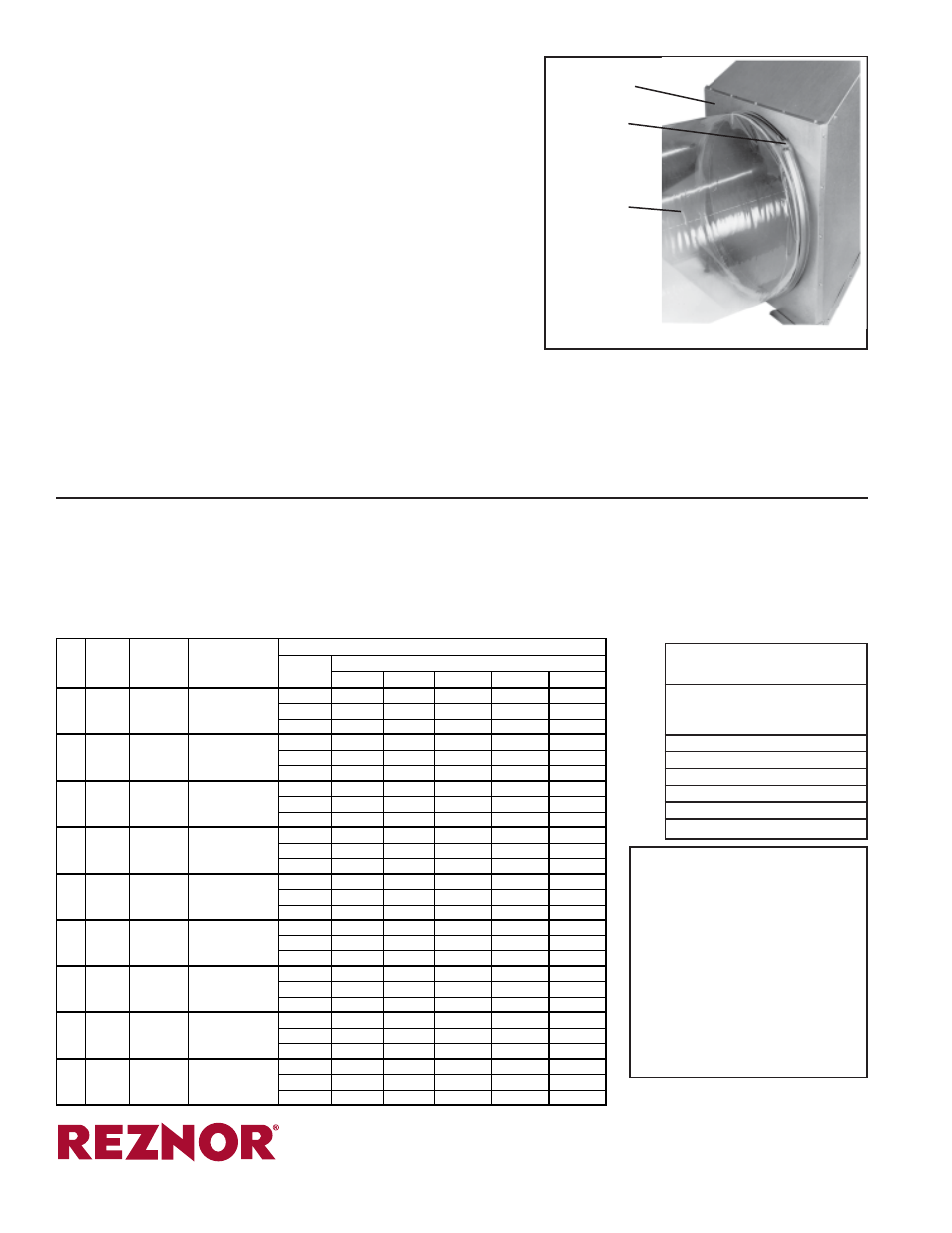
7. Install Polytube (See Figure 8)
The polytube adapter is now completed and ready for the field-supplied polytube.
Slip the end of the polytube over the collar under the tightening band. Be sure that the
air delivery holes are pointed in the proper direction. Fasten the band over the
polytube by tightening the adjusting screw.
The polytube should be suspended in accordance with the polytube manufacturer's
recommendations. General recommendations are that the first suspension point be
10 feet from the heater and that additional suspension be provided at approximately
8-foot intervals.
Polytubes are normally supplied as a tube which is open at both ends. The end
opposite the heater must be closed to permit the tube to inflate.
8. Installation Checks
When the installation is completed, the motor load and discharge air temperature
should be checked. Consult the installation manual supplied with the heater for
information on checking motor load and how to make blower speed adjustments.
Discharge
Panel
Band with
Adjusting
Screw
Polytube
Ductwork
Figure 8 - Attach
Discharge Panel
and Polytube
Ductwork
WARNING:
Optional
polytube adapters are to be
used only on units equipped
with a blower. At no time
should the free area in the
polytube be less than the
listed minimum. Failure to
comply with this warning
could result in severe
personal injury, death, and/or
property damage.
Use a temperature measuring device to check the discharge
air temperature. Check the air temperature at a location in
the tube, six to eight feet way from the heater. A tempera-
ture rise range of 55
o
to 65
o
F is recommended. Following
the instructions in the heater manual, adjust the speed of the
blower to achieve the desired range while maintaining motor
current draw below the full load amperes shown on the
motor rating plate.
Conversion Table
(Diameter to Area)
Diameter
Area
of the Hole
of the Hole
(inches)
(square inches)
2-1/2
4.91
2-1/4
3.98
2
3.14
1-7/8
2.76
1-1/2
1.76
1
0.785
POLYTUBE SELECTION - Polytube selection is the responsibility of the installer. Different grades, hole positions, hole sizes, and lengths are
available. Some local code authorities require that polytube material be a listed material. Consult code authority having jurisdiction and polytube
supplier to determine the appropriate polytube material and recommended methods of suspension. Polytubing can be obtained from a supply
distributor such as FOF Products, Inc., P. O. Box E, 1505 Racine Street, Delavan,WI 53005; Acme Engineering company, P. O Box 978, Muskogee,
OK 74402; or any local greenhouse supply distributor.
The total open or free area of the polytube is important. Polytube suppliers have a great deal of flexibility in placement and sizing of holes. Too small
of a free area will cause overheating. Excessive open area may not permit the tube to inflate. See the table below for a guide in hole size and location.
Spacing and hole size may be varied, but free area must not be less than shown for your heater size.
(800) 695-1901, www.RezSpec.com
©2014 Reznor, LLC. All rights reserved.
Printed in the U.S.A.
MANUFACTURER OF GAS, OIL, ELECTRIC HEATING AND VENTILATING SYSTEMS
Trademark Note: Reznor
®
is registered in the United States and other countries.
0514 POD OG Form I-B-PS (Version 0.1)
CFM at Polytube
Minimum Free
Suggested Hole Sizes and Locations
Size .25"
Diameter
Area (square
Length of Polytube
ESP
(inches)
Inches)
50 Ft
75 Ft
100 Ft
125 Ft
150 Ft
Number
37pairs
75 pairs
75 pairs
75
925
18
110
Diameter
1-1/2"
1"
1"
Spacing
16"
12"
16"
Number
50 pairs 50 pairs 100 pairs
94 pairs
100 1235
18
145
Diameter
1-1/2"
1-1/2"
1"
1"
Spacing
12"
18"
12"
16"
Number
40 pairs 60 pairs
60 pairs
125 pairs
125 1540
18
185
Diameter
1-7/8"
1-1/2"
1-1/2"
1"
Spacing
15"
15"
20"
12"
Number
40 pairs 60 pairs
60 pairs
125 pairs
130 1600
24
190
Diameter
1-7/8"
1-1/2"
1-1/2"
1"
Spacing
15"
15"
20"
12"
Number
50 pairs 50 pairs
75 pairs
75 pairs
75 pairs
165 2035
24
240
Diameter
1-7/8"
1-7/8"
1-1/2"
1-1/2"
1-1/2"
Spacing
12"
18"
16"
20"
24"
Number
42 pairs 42 pairs
60 pairs
60 pairs
100 pairs
200 2465
24
300
Diameter
2-1/4"
2-1/4"
1-7/8"
1-7/8"
1-1/2"
Spacing
14"
21"
20"
25"
18"
Number
40 pairs 60 pairs
60 pairs
60 pairs
60 pairs
250 3085
24
360
Diameter
2-1/2"
2"
2"
2"
2"
Spacing
15"
15"
20"
25"
30"
Number
75 pairs 75 pairs
75 pairs
75 pairs
75 pairs
300 3700
24
425
Diameter
2"
2"
2"
2"
2"
Spacing
9"
12"
16"
20"
24"
Number
60 pairs 60 pairs
60 pairs
100 pairs 100 pairs
400 4935
24
550
Diameter
2-1/2"
2-1/2"
2-1/2"
1-7/8"
1-7/8"
Spacing
10"
15"
20"
15"
18"
Holes