Reznor UDBS Option - Installation - Polytube Adapter Instructions User Manual
Page 3
Form RZ-NA I-UD-PA, P/N 203188 Rev 4, Page 3
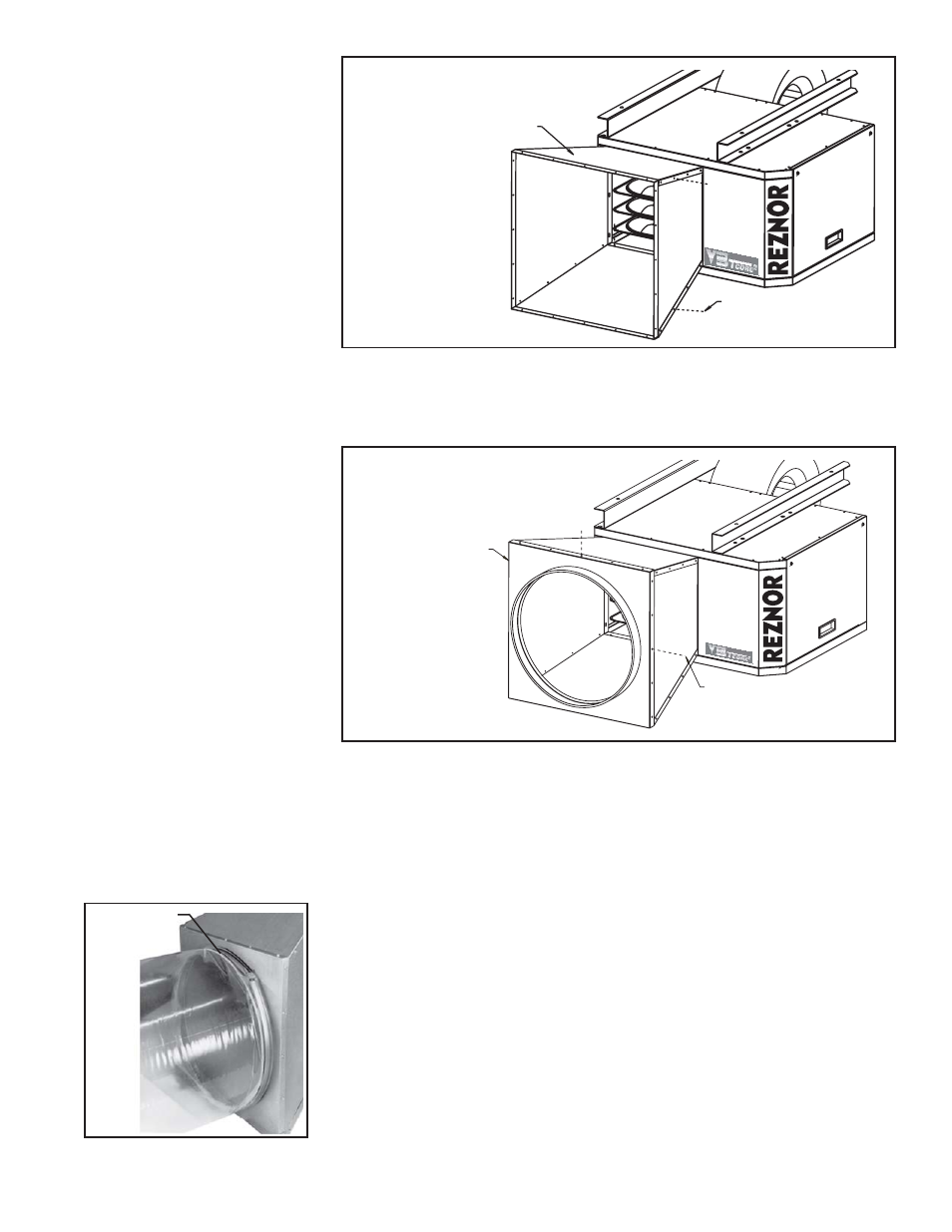
FIGURE 3 - Attach
Adapter Top and Bottom
Sheetmetal Screws
Adapter Top
Adapter
Bottom
®
6. Attach the Discharge Panel (See FIGURE 4)
Slide the discharge panel over the front of the “box” formed by the sides, top,
and bottom adapter panels. Attach at all of the holes across the top, bottom,
and sides.
Sheetmetal Screw
Discharge
Panel Assy
®
FIGURE 4 - Attach
Adapter Top and Bottom
7. Attach Polytube (See FIGURE 5)
The polytube adapter is now complete and ready for the field-supplied
polytube ductwork. Being sure that the air delivery holes are pointed in the
proper direction, slip the end of the polytube over the collar under the tighten-
ing band. Fasten the band over the polytube by tightening the adjusting
screw.
The polytube should be supported in accordance with the polytube
manufacturer’s recommendations. General recommendations are that the first
suspension point be 10 ft (3M) from the heater and that additional suspension
be provided at approximately 8-ft (2.4M) intervals.
Polytubes are normally supplied as a tube which is open at both ends. The
end opposite the heater must be closed to permit the tube to inflate.
8. Installation Checks
When the installation is completed, the motor load and discharge air tempera-
ture should be checked. Consult the installation manual supplied with the
heater for information on checking motor load and how to make blower speed
adjustments.
Use a thermometer to check the discharge air temperature. Check the air
temperature at a location in the tube, six to eight feet (1.8-2.4M) from the
heater. A temperature rise range of 55° to 65°F is recommended. Following
FIGURE 5 - Attach the
Polytube
Band with
Adjusting
Screw