Installation instructions (cont’d) – Reznor UDAS in sizes 30 through 125 Option - Installation - Ceiling Suspension Kit User Manual
Page 2
Form I-UD&APD Series-CS (11-14) PN 197096R1, Page 2
Installation Instructions (cont’d)
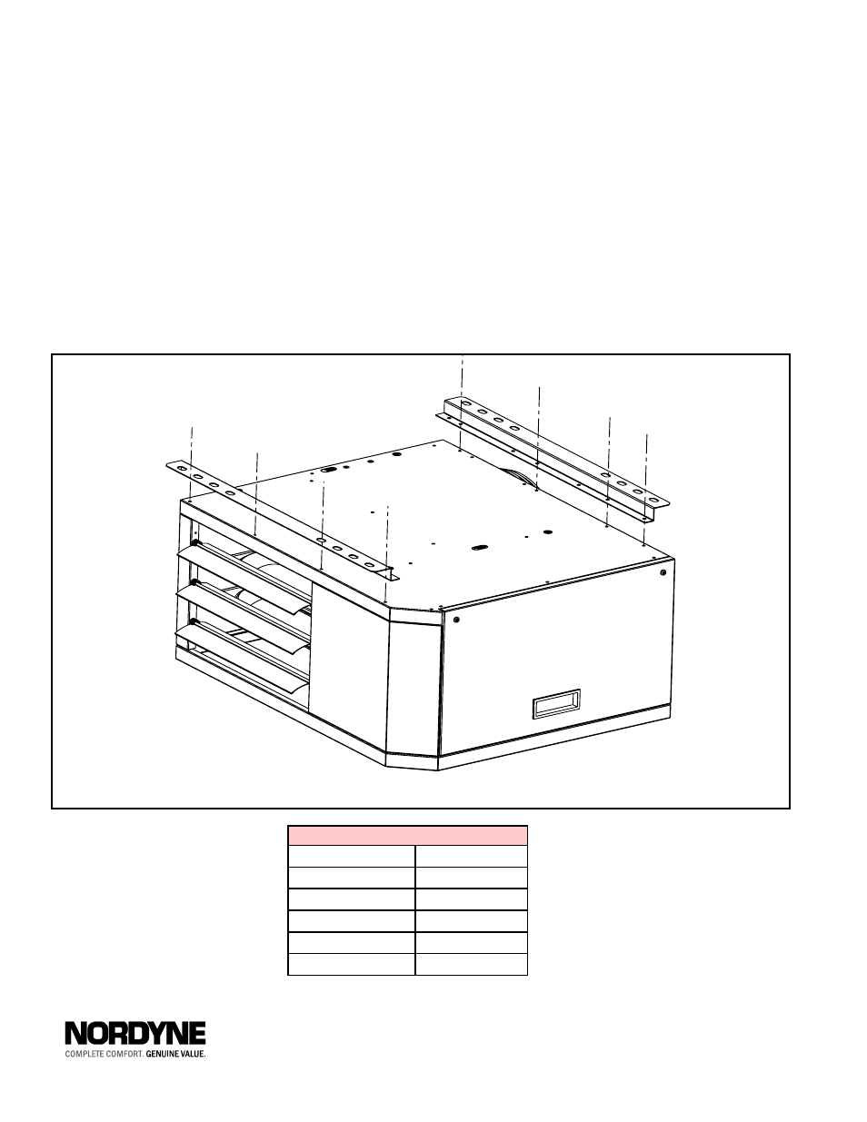
(UDAP Model shown in illustration)
Figure 1 - Attach ceiling suspension
brackets to top, across front and
rear of the heater
Specifications & illustrations subject to change without notice of incurring obligatons.
©2014 Nortek RCH Group. All rights reserved.
All marks are the property of their respective organizations.
O’Fallon, MO I Printed in U.S.A. (11/14)
D300516 SKU322E-1214 FORM I-UD&APD Series-CS (11-14), PN 197096R1
Required Minimum Clearances
Top
1” (25 mm)
Flue Connector
6” (152 mm)
Access Panel
18” (457 mm)
Non-Access Side
1” (25 mm)
Bottom
1” (25 mm)
Rear
18” (457 mm)
3) Along the rear edge of the top of the heater cabinet, find four sheet-
metal screws. Remove all four and keep.
4) Position the other suspension angle along the top edge of the cabinet
as illustrated, lining it up with four holes. Using the four screws re-
moved in Step 3, attach the suspension angle to the top of the heater.
The heater may now be lifted and attached directly to the ceiling structure
using a minimum of two anchor points per suspension angle.
When lifting the heater into position, support the bottom with plywood or
other appropriately placed material. If the heater is not supported, damage
could occur.
The suspension angles are designed to provide the required top clearance.
All clearances must be maintained.