PS Engineering PMA8000BT NUI Installation Manual User Manual
Page 25
PS Engineering
PMA8000BT Audio Selector Panel and Intercom System
Installation and Operator’s Manual
200-890-1702
Page 3-3
New, April 2011
Booth." Only the pilot will hear the telephone, and only he will be heard. He will also have access to Com 1
or 2, and will transmit on that radio using the PTT. All selected audio is provided to the pilot.
NOTE
Because the cell-phone uses an intercom circuit, all stations on that circuit will lose intercom capability
when the cell phone is in use.
3.4.1
Cell phone Sidetone
As shipped from PS Engineering, the PMA8000BT does NOT provide cellular telephone sidetone (the us-
er’s voice fed back to the headset). Some cell phones do not provide sidetone. In PMA8000BT audio pan-
els, Telephone sidetone can be enabled by pressing the TEL and ADF buttons for more than one second.
3.5 Speaker Amplifier (5)
The SPR in the lower right section stands for speaker. This switch will place all selected audio on the cock-
pit speaker when this switch is selected. Except for the unswitched audio, the speaker amplifier is not active
in the "Split Mode”.
Unswitched audio, (the inputs dedicated to autopilot disconnect, altimeter warning, etc.) will come through
the speaker regardless of the speaker button position.
Depending on installation, important audio annunciations such as radar altimeter or autopilot disconnect
will come over the speaker even if it is not selected, while other unswitched, but muted inputs, such as GPS
alerts, will only be present if the SPR button is selected. Consult your professional avionics installer for
these important configuration details.
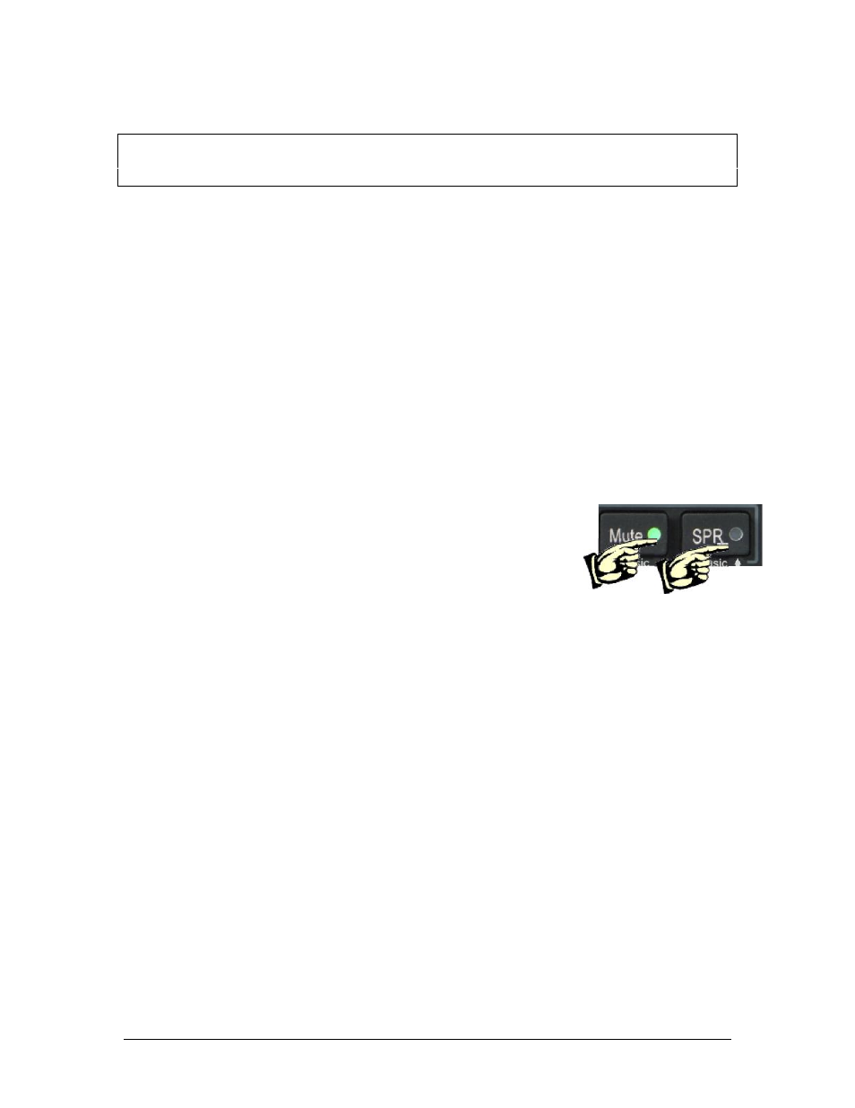
3.5.1.1
Public Address Function
To access PA function, press the Mute and SPR buttons simultaneously. The
pilot microphone will be heard on the speaker when the pilot PTT is used. The
copilot can continue to use the selected com radio while the pilot will now be
heard over the speaker. During Public Address, the Mute and SPR buttons will
flash. To exit PA mode, push Mute and SPR again.
3.6 Marker Beacon Operation (10)
The Marker Beacon Receiver uses visual and audio indicators to alert you when the aircraft passes over a
75 MHz transmitter.
The Blue lamp, labeled “O”, is the Outer Marker lamp and has an associated 400-Hertz 'dash' tone. The
lamp and tone will be keyed at a rate of two tones/flashes per second when the aircraft is in the range of the
Outer Marker Beacon.
The Amber lamp, labeled “M”, is the Middle Marker lamp and is coupled with a 1300 Hertz tone. It is
keyed alternately with short 'dot' and long 'dash' bursts at 95 combinations per minute.
The White lamp, labeled “I”, is the Inner marker and has a 3000 Hertz 'dot' tone. The lamp and tone will be
keyed at a rate of six times per second.
The audio from the Marker Beacon Receiver can be heard by selecting the "MKR" push-button switch. To
adjust the volume level, there is a service adjustment located on the top of the unit.
A pushbutton is used to set the receiver sensitivity and to test the indicator lamps mute the marker audio.
Use "HI" sensitivity initially. This allows you to hear the outer marker beacon about a mile out. Then touch
the smaller MKR button to switch into Low Sensitivity mode. “LO” sensitivity gives you a more accurate
location of the Outer Marker. Holding the MKR button for one second activates marker test lamp, labeled
"T/M" and illuminates all three lamps simultaneously to assure the lamps (internal and external) are in
working order. TST does not activate MM autopilot sense output. Releasing the button returns to the last
sensitivity.
Pressing the marker mode select (“T/M”) for one second will also cause the marker audio to mute for that
beacon. The next beacon received will re-activate the audio.