PS Engineering PMA8000BT NUI Installation Manual User Manual
Page 13
PS Engineering
PMA8000BT Audio Selector Panel and Intercom System
Installation and Operator’s Manual for units with serial number CBT1561 and above
200-890-1702
Page 2-6
New, April 2011
Cellular telephones installed in or carried aboard airplanes, balloons or any other type of aircraft must not
be operated while such aircraft are airborne (not touching the ground). When any aircraft leaves the ground,
all cellular telephones on board that aircraft must be turned off.
PS Engineering, Inc. does not endorse using unapproved cellular telephone equipment in flight, and takes
no responsibility for the user’s action.
PS Engineering does not guarantee compatibility with personal cellular telephones. For a list of phones that
have been tested, visit
http://www.ps-engineering.com/support
.
2.4.11 Public Address Mode
By pressing the Mute and SPR pushbuttons at the same time, the PMA8000BT will be placed into public
address (PA) mode. In this mode, the pilot will be talking over the cockpit speaker when he presses his PTT
switch. Copilot will still continue on the selected COM radio.
When the discrete Output is enabled, J2 Pin 19 will go low when in PA mode, providing a logic level that
can be used to incorporate a speaker-switching scheme. This 50 mA circuit (10Ω Z) can control a switching
means such as a relay that would transfer the speaker output amplifier from the cockpit speaker to drive
another cabin speaker. If the PA mode is used with a microphone in proximity to an active cockpit speaker,
feedback might result.
To enable the PA discrete Output located at the rear connector, the internal configuration jumper, J4,
MUST be placed across both pins in the header. This jumper is shipped as open from the factory.
2.4.11.1Public Address Output Jumper
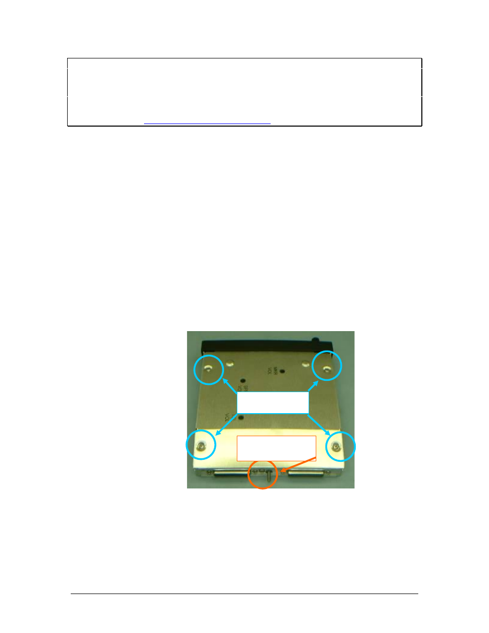
1.
Remove qty. 5 Phillip head screws from the PM8000BT. NOTE: THE SCREW IN THE REAR
OF THE PANEL IS A DIFFERENT LENGTH THAN THE OTHER FOUR. YOU MUST
PUT THE SHORTER LENGTH SCREW BACK IN THE SAME LOCATION OR
DAMAGE WILL OCCUR. See Figure #1.
Figure 2-2 Screw Locations
2.
Move the blue jumper located in the back corner near the sub-D connectors on both pins of J4. See
Figure #2-3.
Long shaft screws
Short shaft screw
if installed