PS Engineering PMA8000BT NUI Installation Manual User Manual
Page 14
PS Engineering
PMA8000BT Audio Selector Panel and Intercom System
Installation and Operator’s Manual for units with serial number CBT1561 and above
200-890-1702
Page 2-7
New, April 2011
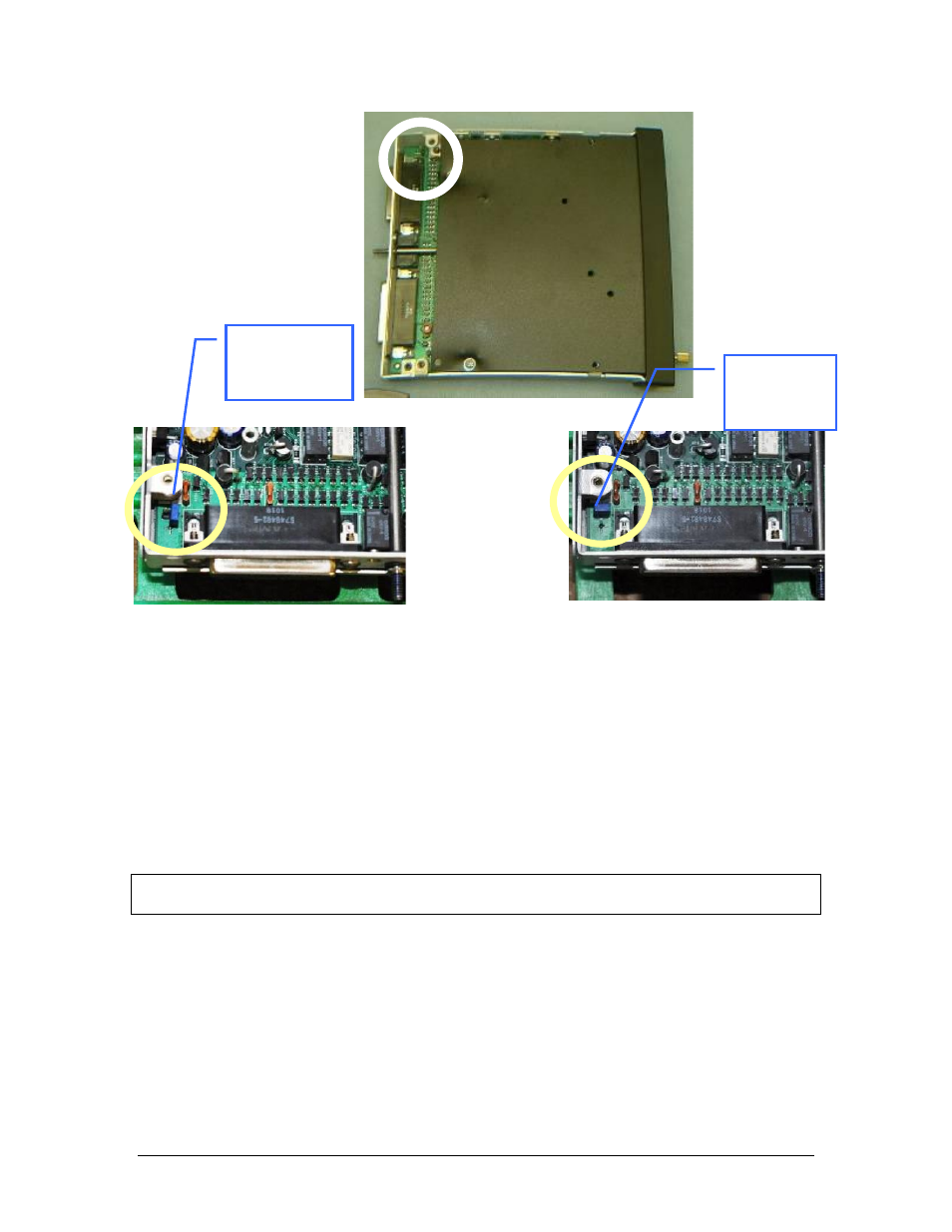
Figure 2-3 Jumper Location
4.
Place the lid back on the unit, aligning holes.
5.
Install and tighten qty. 4 long thread screws into the lid, and one short screw on the rear (if in-
stalled).
2.4.12 PA Mute (J2, Pin 12)
Pin 12 of J2 is a TTL logic output that is pulled low during PTT operation.
2.4.13 Miscellaneous Logic Output (J2, Pin 18)
Pin 18 of the J2 connector is pulled to ground whenever the AUX button is depressed. This serves as a con-
trol line for external devices, such as an entertainment system that the pilot wishes to control.
This pin can also be used to control passenger (Music 2) Karaoke Mode, by connecting to pin 13 of the J2.
NOTE
J2, Pin 18 should NOT be used if the AUX is going to be used to switch DME or auxiliary audio.
2.4.14 Audio Active Output
Pin 24 on the J1 connector (and PA Mute Pin 12 on J2) should be connected to Apollo CNX80 for audio
message prioritization, refer to CNX80 installation manual for details.
2.5 Intercom wiring
See Appendix C and D for intercom connection configurations. It is critical to the proper operation of this
system to have this connector wiring made in accordance with these diagrams. Use 2- and 3-conductor,
MIL-spec cable as shown. Connect the shields at the audio panel end only, and tie to the audio low inputs as
shown.
Jumper Off (no
PA mode)
Jumper On
(PA mode
enabled)