Pa mute (j2, pin 12), Intercom wiring, Entertainment inputs – PS Engineering PMA8000MP3-Avidyne User Manual
Page 14: Ntercom wiring, Ntertainment, Nputs
PS Engineering
PMA8000B-MP3Avidyne Version (-0403) Audio Selector Panel and Intercom System
Installation and Operator’s Manual
200-890-0403
Page 2-7
Rev. 4, Jan. 2011
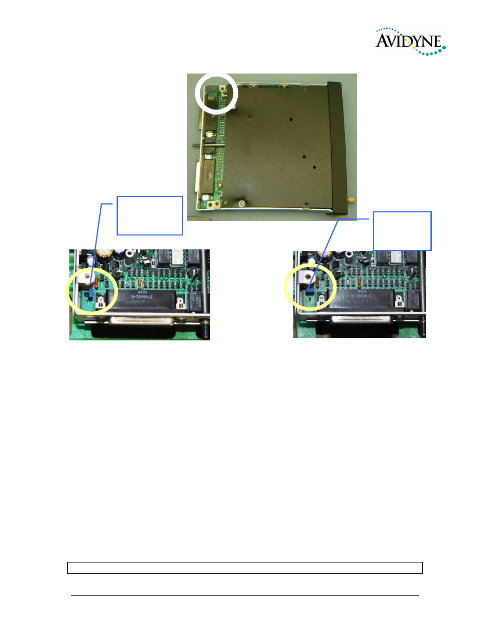
Figure 2-3 Jumper Location
4. Place the lid back on the unit, aligning holes.
5. Install and tighten qty. 4 long thread screws into the lid, and one short screw on the rear.
2.4.12 PA Mute (J2, Pin 12)
Pin 12 of J2 is a TTL logic output that is pulled low during PTT operation. This output from the audio
panel is sometimes used as an input to external public address system to prevent PA feedback during
transmissions
2.5 Intercom wiring
See Appendix C and D for intercom connection configurations. It is critical to the proper operation of this
system to have this connector wiring made in accordance with these diagrams. Use 2 - and 3-conductor,
MIL-spec cable as shown. Connect the shields at the audio panel end only, and tie to the audio low inputs
as shown.
2.5.1
Entertainment Inputs
In addition to the internal MP3 player, the PMA8000B-MP3 has two INDEPENDENT music inputs,
PLUS a front mounted jack that is connected to Entertainment 1. Entertainment input number 1 is J2 pins
23 (left channel) and 24 (right channel), with respect to pin 25, and Entertainment number 2 is connected
to 26 (left channel), 27 (right channel), with r espect to 28. Refer to Section 3.11.3 for more information.
NO T E
Jumper Off (no
PA mode)
Jumper On
(PA mode
enabled)