Backlighting, Unswitched inputs, Avidyne entegra special interface – PS Engineering PMA8000MP3-Avidyne User Manual
Page 12: Acklighting, Nswitched inputs, Vidyne, Ntegra, Pecial, Nterface
PS Engineering
PMA8000B-MP3Avidyne Version (-0403) Audio Selector Panel and Intercom System
Installation and Operator’s Manual
200-890-0403
Page 2-5
Rev. 4, Jan. 2011
2.4.8
Backlighting
The PMA8000B-MP3 has an automatic dimming of the pushbutton annunciation LEDs and marker lamps
controlled by a photocell. Control of the unit backlighting is through the aircraft avionics dimmer For 14
V aircraft, connect J2 Pins 6 and 7 to the aircraft dimmer bus, and pin 5 to groun d. For 28-volt systems,
connect pin 7 to the aircraft dimmer, and pins 5 and 6 to ground.
If an external dimmer control is not used, a constant back light illumination can be established for nigh t-
time viewing. Pin 6 or 7 (depending on system voltage) must be tied to power (J2, pin 8 or 9) for the back
lighting system to work. The photocell mounted in the unit face will automatically adjust the intensity of
the push-button annunciator LEDs.
2.4.9
Unswitched inputs
J1, pins 31, 29 and J2 pin 15 are unswitched, unmuted (by transmitter keying), inputs # 1, 3 and 4, r e-
spectively. These inputs are presented to the pilot and copilot regardless of the audio configuration, and
will always mute the entertainment inputs. These 510Ω inputs can be used for altimeter DH audio , GPS
waypoint audio, autopilot disconnect tones, or any other critical audio signal. Unswitched #1 is always
presented to the speaker, plus to the crew headphones, and is available to the pilot in fail -safe (off) mode.
Unswitched 3 and 4 inputs are always presented to the crew headphones and to the aircraft speaker.
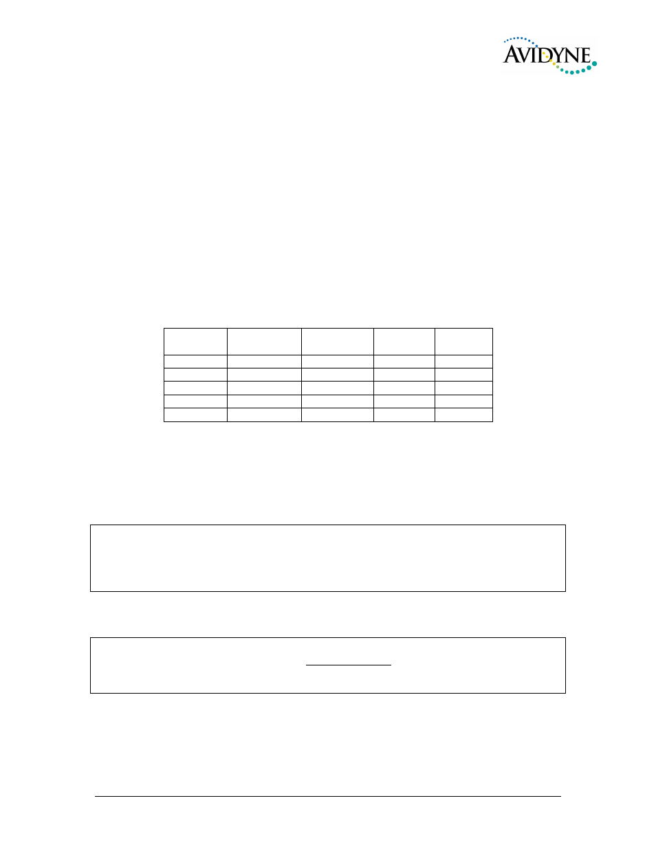
Unswitched
Input
Hear in
Fail Safe
Hear in
Crew Headset
SPR button
Select
Gain
1
Yes
Yes
No
1:1(fixed)
2
No
Yes
Yes
1:1(fixed)
3
No
Yes
No
Adjustable
4
No
Yes
No
1:1(fixed)
5 (jack)
No
Yes
No
1:1(fixed)
Table 2-2 Unswitched input table
Unswitched #2, J1 pin 44 is unswitched is always connected to the Pilot’s headphone. However, this
unswitched audio is only presented to the aircraft speaker when the SPR push button has been selected.
The audio low for unswitched #4 (J2, pin 15) should be connected to a convenient audio low. However,
this should NOT be connected to Music Low.
Unswitched #1 is presented to the pilot headphone in fail-safe (off) mode.
NOTE
Inputs 1, 2 and 4 are fixed (1:1), and any audio level adjustments must be made at the input source.
Unswitched #3 has a variable adjustment control located on the bottom side of the unit. This control a l-
lows you to control the volume level of that unswitched input from 50% to 200% of the input level. Refer
to Adjustments section.
The front panel jack can be configured to act as a fifth unswitched input. When configured through the
front panel function switches (see operational section), the audio input to this jack will be presented to the
pilot and copilot headset, and not muted.
NOTE
The front-mounted utility jack is intended for portable equipment that is advisory in nature. It is NOT
INTENDED for use as a primary warning channel. Audio of importance MUST ALWAYS be hard-wired
into the unswitched inputs of the audio panel.
2.4.10 Avidyne Entegra Special Interface
The dedicated Avidyne Entegra (Release 9) interface is shown in Appendix C. For J1, connect Pins 7 and
8 to P1144 pins 43 & 48 (Mon 1), and Pins 21 and 22 to P2144 Pins 43 & 48 (Mon 2). Connect the
Marker discrete outputs, J1 Pins 36 (Inner), 37 (Outer) & 38 (middle) to P1121 (#1 IFD) and P2121 (#2
IFD) Pins 82, 62, and 63, respectively.